

Welcome to Module 6 of Mastering UML with Visual Paradigm AI: From Natural Language to Professional System Blueprints. Having built a comprehensive behavioral picture in Module 5—through detailed interactions, layered sequences, and rich state lifecycles—we now shift perspective to the physical realization of the system: how the software is packaged, deployed, and executed in real-world infrastructure.
This module focuses on infrastructure and deployment modeling, the final layer that bridges abstract design to concrete operation. These models answer essential late-stage questions: What are the reusable software components and their interfaces? How are artifacts (executables, libraries, containers) deployed across nodes (servers, cloud instances, edge devices)? What are the physical runtime dependencies and communication paths? How do time-critical behaviors manifest in the deployed environment?
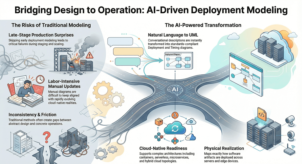
Traditional deployment and infrastructure modeling often occurs late – or not at all – leading to surprises during staging, scaling, or production incidents. Manually creating Component, Deployment, and Timing Diagrams is labor-intensive, prone to inconsistency, and difficult to keep aligned with evolving requirements and cloud-native realities.
Visual Paradigm’s AI ecosystem brings these diagrams into the same fast, conversational, standards-compliant workflow used throughout the course. Natural language descriptions of architecture, cloud topology, or timing constraints are instantly transformed into precise UML artifacts—ready for review, refinement, and integration with modern deployment practices (containers, serverless, microservices, hybrid cloud).
Overview
The primary goals of Module 6 are to:
- Model the modular software structure using Component Diagrams—showing reusable parts, interfaces, ports, connectors, and dependencies.
- Define the physical deployment topology with Deployment Diagrams—mapping artifacts to nodes (EC2 instances, Kubernetes pods, Lambda functions, databases) and illustrating runtime relationships (communication paths, protocols, hardware/software nodes).
- Capture precise timing behavior in Timing Diagrams—documenting time-dependent constraints, durations, state changes over time, and real-time requirements critical for performance-sensitive or embedded systems.
- Ensure these models remain tightly traceable to the static structure (classes/packages), behavioral interactions (sequences/state machines), and functional requirements (use cases).
Key AI-Powered Techniques You Will Master
- Component Architecture Modeling Describe modular software parts (microservices, libraries, APIs, databases) in plain English. The AI Chatbot generates Component Diagrams showing provided/required interfaces, ports, connectors, subsystems, and dependency relationships—ideal for cloud-native, service-oriented, or modular monolith designs.
- Deployment Mapping to Real Infrastructure Specify your target environment (e.g., AWS, Azure, Kubernetes, on-prem hybrid). AI produces Deployment Diagrams visualizing:
- Artifacts (JARs, Docker images, executables, configuration files)
- Nodes (virtual machines, containers, serverless functions, load balancers, databases)
- Communication links (HTTP, gRPC, message queues)
- Cloud-native icons and stereotypes when appropriate
- Deployment constraints (e.g., replication, zones, scaling rules)
- Specialized Timing Models For systems where precise timing matters (real-time, IoT, financial trading, embedded), describe temporal requirements in natural language. AI generates Timing Diagrams showing:
- State or value changes over time
- Duration constraints
- Time intervals and deadlines
- Concurrency and synchronization points
By the end of this module, you will be able to:
- Produce clean, standards-compliant Component Diagrams that define modular software boundaries and contracts.
- Create realistic Deployment Diagrams that map your design to actual (or planned) infrastructure—cloud, hybrid, or on-premises.
- Document time-critical behavior with Timing Diagrams when millisecond-level precision or deadlines are non-negotiable.
- Keep infrastructure views traceable and consistent with earlier models (classes, packages, sequences, states).
- Use these diagrams to support DevOps discussions, cloud cost estimation, security reviews, and production readiness assessments.
These models represent the physical incarnation of everything built so far. They reveal deployment risks, scalability limits, operational dependencies, and performance considerations—bridging the gap between architecture and operations.
With AI handling notation, iconography, layout intelligence, and iterative refinement, you can focus on strategic choices: microservices granularity, cloud provider selection, fault tolerance, observability, and alignment with business SLAs.
The journey from abstract blueprint to deployable reality is now complete in its core dimensions. In the final modules, we explore advanced frameworks, architectural integrity checks, code/database integration, and global collaboration – turning models into living, production -driving assets. Let’s bring the system into the real world.