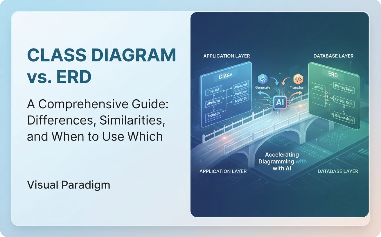
When designing complex software systems, engineers and database architects often face a fundamental structural choice: Should you start with a UML Class Diagram or an Entity-Relationship Diagram (ERD)? While both diagrams visualize data structures and connections, they serve distinct roles in software architecture and database engineering.
At a Glance: What Are Class Diagrams and ERDs?
Understanding the distinction between application behavior and persistence storage is the key to choosing between these two visual modeling tools:
- UML Class Diagram: A structural diagram in the Unified Modeling Language (UML) that models object-oriented software architecture. It represents classes, their attributes, behavioral operations (methods), and encapsulation rules (visibility).
- Entity-Relationship Diagram (ERD): A data modeling technique used to visualize the structural logical or physical schema of a database. It focuses strictly on data entities, their attributes, and relationships (such as primary and foreign key links).
Key Differences Between Class Diagrams and ERDs
Although they may look similar on a superficial level, Class Diagrams and ERDs differ fundamentally in purpose, notation, and level of abstraction:
| Feature | UML Class Diagram | Entity-Relationship Diagram (ERD) |
|---|---|---|
| Primary Focus | Software architecture & Object-Oriented Design (OOD) | Database schema design & Data persistence |
| Key Elements | Classes, Attributes, Operations (Methods), Interfaces | Entities, Attributes, Primary Keys (PK), Foreign Keys (FK) |
| Behavior Modeling | Yes: Captures functions, methods, and business logic | No: Purely static; models stored data, not actions |
| Encapsulation | Supports visibility markers (+ public, - private, # protected) |
No concept of visibility (all table columns are accessible to queries) |
| Relationships | Association, Aggregation, Composition, Inheritance, Realization | One-to-One, One-to-Many, Many-to-Many (using Crow’s Foot / Chen notation) |
| Code Linkage | Generates object code (Java, C#, C++, Python) | Generates DDL SQL scripts (MySQL, PostgreSQL, Oracle) |
1. Operations and Methods vs. Static Data Storage
The biggest technical difference lies in **behavior**. A class diagram compartment explicitly includes operations (e.g., calculateDiscount(), processPayment()). An ERD strictly focuses on data fields (e.g., customer_id, email_address) without specifying how that data is processed.
2. Inheritance vs. Foreign Keys
In class diagrams, object-oriented concepts like **inheritance (generalization)** let child classes inherit properties from a parent class. ERDs do not natively support object inheritance; instead, they establish relational integrity using **Primary Key (PK)** and **Foreign Key (FK)** references across relational tables.
Similarities Between Class Diagrams and ERDs
Despite their operational differences, Class Diagrams and ERDs share significant conceptual overlap, especially during early system design:
- Structural Blueprinting: Both map out the core domain entities of a system (e.g., a
Userclass in UML closely mirrors auserstable in an ERD). - Multiplicity and Cardinality: Both express numerical constraints between entities (e.g., “1 to Many” in ERDs vs.
1..*multiplicity in Class Diagrams). - Foundation for ORMs: Object-Relational Mapping (ORM) frameworks (like Hibernate, Entity Framework, or Prisma) directly bridge class models to ERD schemas.
When to Use Which: Decision Framework
Use a UML Class Diagram when you are:
- Designing the domain logic and class structures of an object-oriented application.
- Defining class methods, interface contracts, and behavioral inheritance hierarchies.
- Communicating system structure with software developers and application architects.
- Generating application code skeletons in languages like Java, C#, or C++.
Use an ERD when you are:
- Designing a relational database schema or normalizing database tables.
- Defining primary keys, foreign key constraints, and index structures.
- Communicating with Database Administrators (DBAs) and data engineers.
- Writing or auto-generating SQL DDL migration scripts.
Accelerating Diagramming with Conversational AI
Transitioning between application logic and database schema design can slow down development teams. Modern engineering workflows utilize AI diagramming assistants to instantly generate both Class Diagrams and ERDs directly from natural language prompts.
With the Visual Paradigm AI Diagramming Chatbot, you can describe your domain requirements once and ask the AI to generate either notation:
Prompt for Class Diagram: “Generate a UML class diagram for an online library system including Book, Member, Loan, and Fine classes with methods.”
Prompt for ERD: “Convert this library system into an Entity-Relationship Diagram showing primary and foreign keys for database implementation.”
By leveraging our syntactically trained model, you eliminate syntax errors across both UML and ERD standards. Learn more on our dedicated AI Class Diagram Generator Feature Page.
Bridging the Gap: The Visual Paradigm AI Ecosystem
Creating the initial diagram is only step one. Visual Paradigm provides an integrated ecosystem that allows you to take your AI-generated models through the entire development lifecycle:
1. Document Schemas in OpenDocs
Export your ERD or Class Diagram to Visual Paradigm OpenDocs to build interactive data dictionaries and architectural specifications accessible across your organization.
2. Touc-up with VPasCode
Because the AI Chatbot outputs clean declarative code (like PlantUML, Mermaid, or Graphviz), you can take your structural diagrams directly into VPasCode for minor touch-ups.
3. Visual Editing in VP Online
Need to tweak relationships on an online canvas? Push your AI-generated diagrams directly into VP Online for flexible drag-and-drop editing and team whiteboarding.
4. Full Lifecycle Modeling in VP Desktop
For enterprise-grade database engineering and software design, import your AI Chatbot creations into Visual Paradigm Desktop. Perform reverse-engineering on existing SQL databases or codebases, map ORMs, and run automated code generation.