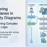
Manual diagramming can be a bottleneck during software architecture design and business process engineering. Translating complex system logic, conditional branching, and multi-actor swimlanes into accurate visual models takes valuable time. Generative AI has transformed this process: by crafting structured natural language text prompts, you can automatically generate verified UML Activity Diagrams and PlantUML code in seconds. This guide walks you through the step-by-step prompt engineering techniques, structural patterns, and real-world workflows to turn plain text into publication-ready activity diagrams.
1. The Fundamentals of Prompt Engineering for UML Activity Diagrams
When you ask an AI model to build a UML Activity Diagram, the quality of the output depends on how effectively you communicate system semantics. An unstructured prompt like “draw an e-commerce checkout diagram” often leads to generic, incomplete flows. In contrast, specifying actors, decision criteria, parallel threads, and boundary conditions enables the AI engine to generate accurate, syntactically sound models.
Why Text-to-Diagram Prompting Works
- Declarative Efficiency: You define what happens in the workflow rather than spending hours manually placing boxes and drawing connector lines.
- Instant Code Generation: AI models convert natural language directly into declarative formats like PlantUML or Mermaid, making diagrams easy to store and version control.
- Rapid Refinement: Modifying a workflow takes seconds—simply prompt the AI with a revision like “Add a 2FA verification step after password authentication.”
2. Anatomy of an Effective UML Activity Diagram Prompt
To produce clean, deterministic UML activity diagrams on the first attempt, your text prompt should include five key architectural elements:
| Prompt Element | Purpose | Example Expression |
|---|---|---|
| Role & Context | Sets the persona and target system scope. | “Act as a Senior Systems Architect modeling a banking transfer process…” |
| Actors / Swimlanes | Defines the organizational or system boundaries. | “Organize the diagram into swimlanes: Customer, Mobile App, Core Banking Engine, and Fraud Service.” |
| Sequential Flow | Lists the step-by-step actions in order. | “1. User initiates transfer. 2. Mobile App validates input format…” |
| Decisions & Branches | Explicitly states ‘if/then/else’ conditions. | “If transfer amount > $10,000, require Fraud Service clearance; otherwise, proceed to ledger processing.” |
| Parallelism (Forks) | Specifies concurrent background tasks. | “In parallel, update user balance, send push notification, and log audit trail.” |
3. Step-by-Step Guide: From Plain Text to Diagram Code
Step 1: Write the Core Narrative
Draft a clear narrative of your business logic or software execution path. Focus on clarity and explicit order of operations.
Step 2: Submit to the AI Diagramming Chatbot
Pass your structured prompt to the AI UML Activity Diagram Chatbot. The chatbot parses the narrative and generates clean PlantUML script.
Step 3: Review the Generated PlantUML Syntax
@startuml
|Customer|
start
:Enter Transfer Details;
:Click Submit;

|Mobile App|
:Validate Form Input;
if (Data Valid?) then ([No])
  :Show Validation Error;
  stop
else ([Yes])
  |Core Banking Engine|
  :Check Account Balance;
  if (Sufficient Funds?) then ([No])
    :Return Insufficient Funds Error;
    stop
  else ([Yes])
    fork
      :Debit Sender Account;
      :Credit Recipient Account;
    fork again
      :Generate Transaction Receipt;
    end fork
  endif
endif

|Mobile App|
:Display Success Confirmation;
stop
@umlend
Step 4: Visualize and Iterate
Render the generated code instantly into a visual Activity Diagram. If a step is missing, simply chat with the AI tool to adjust the logic.
4. Prompting for Complex Structures (Swimlanes, Forks, and Exceptions)
Modeling Parallel Execution (Forks & Joins)
To instruct the AI model to create parallel processing threads, use explicit keywords like “concurrently”, “in parallel”, or “fork into simultaneous tasks”.
Prompt snippet: “Upon order payment approval, execute three parallel tasks: 1) Reserve inventory in Warehouse API, 2) Charge credit card via Payment Gateway, 3) Generate PDF Invoice in Billing System. Rejoin all threads before updating Order Status to Processing.”
Handling Exception & Error Fallback Loops
Ensure your prompt covers fail states so the generated diagram doesn’t end abruptly on errors.
Prompt snippet: “If API authentication fails, retry up to 3 times with exponential backoff. If all retries fail, route execution to Emergency Notification Handler and log critical system event.”
5. Ready-to-Use Prompt Templates for Common System Workflows
Template A: User Authentication & OAuth2 Login Flow
Act as a Software Architect. Generate a PlantUML activity diagram for a User Authentication flow with 2FA.
Swimlanes: User, Frontend Application, Identity Provider (IdP), SMS Gateway.
Process:
1. User submits login credentials on Frontend Application.
2. Frontend sends authentication request to IdP.
3. If credentials invalid, return error to User and stop.
4. If credentials valid, IdP generates a 6-digit 2FA code.
5. IdP sends code via SMS Gateway while Frontend prompts User for 2FA input.
6. User inputs 2FA code.
7. If code matches within 5 minutes, issue JWT Token and redirect to Dashboard; otherwise, display expired code error.
Template B: Order Fulfillment & Inventory Allocation
Generate a UML activity diagram for an E-Commerce Order Fulfillment process using PlantUML.
Swimlanes: Customer, Order Service, Inventory Service, Shipping Service.
Process:
1. Customer places order.
2. Order Service queries Inventory Service for item availability.
3. If out of stock, trigger 'Backorder Notification' to Customer and exit.
4. If in stock, lock inventory items and initiate payment processing.
5. Upon payment success, fork into two parallel tracks:
   - Shipping Service prepares shipping label and assigns courier.
   - Order Service sends order confirmation email to Customer.
6. Once shipping label is created, join threads and update order status to 'Dispatched'.
6. Accelerating Diagramming with Visual Paradigm AI Tools
While general-purpose LLMs can draft basic code, specialized engineering tools provide tighter integration, higher syntax precision, and seamless documentation workflows.
- AI UML Activity Diagram Chatbot: Prompt, preview, and refine activity diagrams in real-time using an intuitive conversational canvas designed specifically for software and business architecture.
- VPasCode (Diagram-as-Code Engine): Edit your PlantUML and Mermaid activity diagram code directly with VPasCode diagram-as-code editor.
- OpenDocs Documentation Suite: Embed AI-generated activity diagrams directly into living technical specifications, PRDs, and Standard Operating Procedures (SOPs) with automatic layout updates.
- Visual Paradigm AI UML Tool: Seamlessly transition between conversational AI modeling and visual drag-and-drop editing across desktop and web environments.
Experience seamless AI-driven diagramming on the web with VP Online Deluxe Edition or on your local workstation with VP Desktop Professional Edition.
7. Frequently Asked Questions
What syntax formats can AI diagramming tools produce from text prompts?
Most AI UML tools, including Visual Paradigm’s AI Chatbot, can output standardized PlantUML script, Mermaid.js code, or direct visual UML models ready for export as SVG, PNG, or PDF.
How do I fix syntax errors in AI-generated PlantUML code?
If the AI output produces a syntax error, feed the error message back to the AI Chatbot with a prompt like: “The PlantUML code gave a syntax error at line 12 near ‘fork again’. Please fix the swimlane partition syntax.” Specialized tools like Visual Paradigm AI validate code automatically to eliminate syntax issues.
Can I convert an activity diagram into a sequence diagram using prompts?
Yes. You can copy your activity diagram prompt narrative and instruct the AI tool: “Convert the above workflow into a UML Sequence Diagram showing message interactions between objects.”
Related Links
- Visual Paradigm VPasCode interactive playground: Try out Visual Paradigm VPasCode in the VPasCode interactive playground
- VPasCode overview: Learn more about VPasCode
- Try out Visual Paradigm AI Diagramming Chatbot: Generate diagrams with AI
- AI Diagramming Chatbot Overview: Learn more about AI Diagramming Chatbot: AI Diagramming Chatbot