Software systems can quickly become complex, tangled webs of code. UML Component Diagrams help software architects, developers, and engineering leads visualize system structure, define high-level module boundaries, and manage technical dependencies before writing a single line of implementation code.
What is a UML Component Diagram?
A UML Component Diagram is a structural Unified Modeling Language (UML) diagram that shows how a software system is broken down into modular, replaceable components and how those components wire together via interfaces.
Unlike lower-level structural diagrams—such as class diagrams, which detail class attributes and operations—a component diagram focuses on higher-level physical or logical software building blocks. Whether you are modeling executable files, library modules, microservices, or database schemas, component diagrams provide the architectural blueprint necessary to communicate system design across teams.
Key Symbols and Notation
Understanding standard UML component diagram notation is crucial for creating readable, unambiguous architectural models. Below are the primary elements used in component modeling:
1. Component
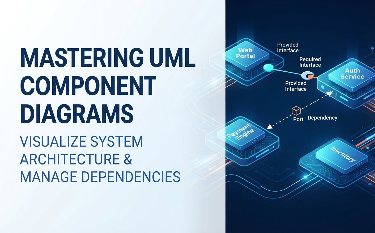
A component represents a modular part of a system that encapsulates state and behavior. In modern UML 2.x notation, a component is drawn as a rectangle containing the component name and a small component icon (a rectangle with two smaller protruding rectangles) in the top right corner, or labeled with the stereotype «component».
2. Interfaces (Provided and Required)
Components communicate with each other through well-defined interfaces. UML uses distinct visual shapes to distinguish between what a component offers and what it consumes:
- Provided Interface (“Lollipop” Notation): Represents the service, API, or contract that a component exposes to other parts of the system. Visualized as a circle attached to the component with a solid line.
- Required Interface (“Socket” Notation): Represents the service or API that a component needs from another component to fulfill its responsibility. Visualized as a half-circle (crescent) attached with a solid line.
- Ball-and-Socket Assembly: When a provided interface meets a required interface, the lollipop fits directly into the socket, visually demonstrating how modules plug together.
3. Ports
A port specifies a distinct interaction point between a component and its external environment, or between a component and its internal sub-parts. It is depicted as a small square placed along the boundary of the component rectangle.
4. Dependencies
A dependency relationship indicates that one component relies on another component to operate. It is depicted as a dashed arrow pointing from the client component (dependent) to the supplier component (provider).
Rules and Structural Best Practices
To keep your architectural documentation clean, maintainable, and effective, follow these fundamental rules when modeling component structures:
- Encapsulate Implementation Details: Components should hide internal details. Expose functionality only through provided interfaces.
- Avoid Tight Coupling: Direct component-to-component dependencies should be minimized. Connect components via interfaces (provided/required) rather than direct hardwired links wherever possible.
- Maintain Single Responsibility: Each component should have a single, coherent purpose (e.g., Auth Service, Payment Adapter, Notification Engine).
- Keep Abstraction Levels Consistent: Avoid mixing high-level system components (e.g., “E-Commerce Web Portal”) with low-level helper classes (e.g., “StringSanitizer”) on the same diagram view.
Accelerating Architecture with an AI UML Tool
Creating component models manually can be time-consuming, especially during early ideation phases when system boundaries shift rapidly. Leveraging a modern AI UML tool transforms this process from manual shape-drawing into conversational modeling.
The Visual Paradigm AI Diagramming Chatbot is an integral component of the broader Visual Paradigm AI Ecosystem. It allows software teams to generate, refine, and document complex system architectures using natural language conversations.
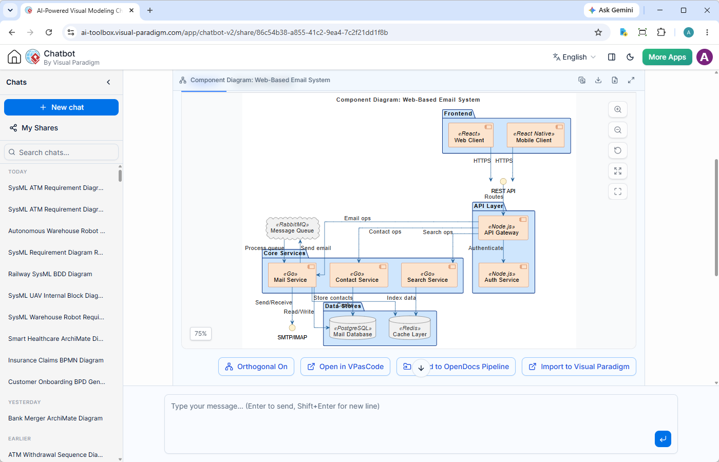
Key Capabilities of the AI Diagramming Chatbot:
- Conversational Diagram Generation: Describe system modules, APIs, and relationships in plain text, and get a syntactically correct UML component diagram instantly.
- Iterative Refinement: Ask the AI to split a monolithic component into smaller microservices, add database interfaces, or extend specific shapes into nested architectural views.
- High-Accuracy Engine: Unlike generic LLM solutions that frequently produce invalid syntax, Visual Paradigm utilizes a well-trained AI model optimized specifically for error-free diagram generation.
- Text-Based Open Formats: Generated diagrams use portable, text-based code standards (such as PlantUML, Mermaid, and Graphviz). You can easily take your diagrams away to edit manually or integrate into your existing development pipelines.
- Artifacts Pane & Navigation: Effortlessly jump through conversational milestones using the Artifacts Pane, which functions as an interactive Table of Contents for your modeling session.
- Session Sharing: Preserve your modeling decisions in persistent chat sessions and share links with teammates for architectural reviews.
Beyond component architecture, the chatbot functions as a versatile AI activity diagram tool, sequence generator, and multi-notation assistant—supporting standard UML, SysML, ArchiMate, C4 Model, BPMN, DFD, SWOT, and flowcharting.
Connecting Component Modeling to the Visual Paradigm Ecosystem
Ideation is only the first step. Once your initial system layout is generated via conversational AI, Visual Paradigm provides seamless tools to take your design into production:
- Keep and Document with OpenDocs: Send your AI-generated component diagrams directly to the Visual Paradigm OpenDocs platform to build comprehensive API specification guides and service boundary documentation.
- Refine with Visual Paradigm VPasCode (Architecture-as-Code): Open your text-based model code directly in VPasCode and make minor touch-ups.
- Collaborate in VP Online: Transition your component diagrams into VP Online’s cloud canvas to run virtual whiteboarding sessions with team members.
- Link Architecture to Code in VP Desktop: Import your high-level component diagrams into Visual Paradigm Desktop to link architectural components directly to concrete implementation classes, ensuring complete traceability.
Getting Started with Visual Paradigm AI
You can begin experimenting with AI-driven component modeling immediately. Visual Paradigm offers a free trial for users to test the AI Chatbot’s capabilities across all supported UML and business diagram types.
Full, unrestricted access to the AI Diagramming Chatbot ecosystem is included with both VP Online Deluxe Edition and VP Desktop Professional Edition licenses.