


Designing complex, time-ordered software interactions and hardware state changes no longer requires tedious manual drawing. Discover how conversational AI streamlines UML Timing Diagram creation directly from plain text prompts.
What is an AI UML Timing Diagram Chatbot?
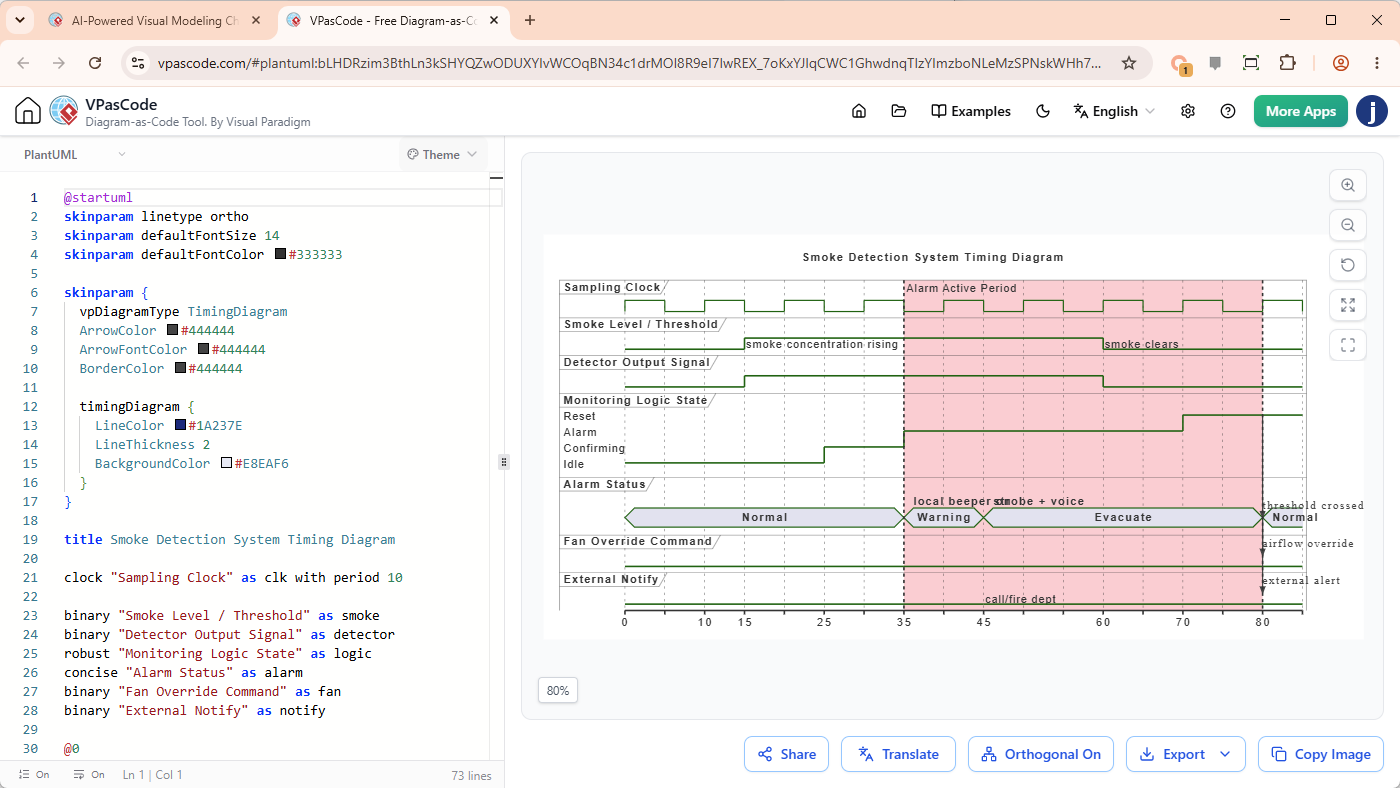
An AI Timing Diagram Chatbot is an AI-powered modeling tool that interprets natural language descriptions of time-ordered events, lifelines, state changes, and time constraints, automatically converting them into syntactically correct UML Timing Diagrams and PlantUML code in real time. The image below provides a screenshot of the chatbot, with a Timing Diagram generated.
The Pain Points of Manual Timing Diagramming
In real-time software systems, embedded systems engineering, and complex message-passing architectures, timing diagrams are essential for visualizing object state shifts across a continuous timeline. However, drawing them manually presents several friction points:
- Complex State Tracking: Synchronizing state transitions across multiple lifelines manually is time-consuming and prone to human error.
- Inaccurate Duration Annotations: Hardcoding delays, clock pulses, and precise execution deadlines visually often leads to inconsistencies between specs and diagrams.
- Maintenance Overhead: Whenever system specifications evolve, updating graphical timelines requires complete redraws, causing documentation rot.
Streamlining Architecture with Visual Paradigm AI
To eliminate manual drawing bottlenecks, engineers and system architects can now leverage the Visual Paradigm AI UML Timing Diagram Generator. By turning natural language prompts into precise visual diagrams and editable code, software development teams can shift their focus from mechanical drawing back to architectural design.
Key Capabilities & Benefits:
- Natural Language Input: Describe lifelines, states, transitions, and duration constraints in plain conversational text.
- Instant Syntax Verification: Built-in AI modeling logic ensures the generated diagram strictly adheres to standardized UML guidelines.
- Diagram-as-Code Integration: Output is backed by readable PlantUML code via VPasCode, making version control and Git tracking seamless.
- Multi-Platform Accessibility: Accessible instantly via web browsers or integrated directly within Visual Paradigm Desktop.
How to Create a Timing Diagram in 3 Steps
- Describe the Interaction: Input your system behavior into the AI chatbot (e.g., “Generate a Timing Diagram for the Smoke Detection System.”).
- Generate the Visual Output: The AI interprets state changes, lifelines, and timing constraints, displaying a complete diagram instantly.
- Refine via VPasCode: Fine-tune timing precision or edit underlying code directly before committing to your version-controlled repository.
References
- Try the AI Diagramming Chatbot — Generate diagrams from natural-language descriptions and explore how AI can help with your modeling work.
- Explore Solutions & Use Cases — See how the AI Diagramming Chatbot can help you solve real-world modeling and diagramming needs across different industries and use cases.
- Learn More About AI Diagramming Chatbot — Explore the chatbot’s features, capabilities, and how it can support your diagramming workflow.
- Stay Updated on AI Diagramming Chatbot — See the latest features, enhancements, and improvements added to the AI Diagramming Chatbot.