



The C4 model is renowned for its simplicity in illustrating high-level software architecture, particularly at Level 2 (Container Diagrams). However, when development teams transition from high-level planning to granular software implementation, a C4 container diagram often lacks the standardized notation required for concrete interface contracts. Converting a C4 container view into a formal UML Component Diagram (Level 3) bridges this gap between architectural vision and executable code.
C4 Container Diagrams vs. UML Component Diagrams
While both frameworks visualize structural building blocks, they serve distinct abstractions in the software design lifecycle:
C4 Container Diagram (Level 2)
A C4 container diagram shows high-level deployable units—such as a single-page web application, a mobile app, a serverside REST API, or a relational database. It answers: “What are the high-level applications and stores that make up the system, and how do they communicate?”
UML Component Diagram (Level 3)
A UML Component Diagram zooms inside an individual container to detail its modular building blocks, provided interfaces (lollipops), required interfaces (sockets), ports, and internal code dependencies. It answers: “How is this specific application container constructed internally, and what are its strict API contracts?”
Step-by-Step Conversion Guide
Follow this structured workflow to transition from C4 containers to formal UML component models:
Step 1: Isolate the C4 Container Boundary
Select a single C4 container (e.g., “Backend API Gateway”) rather than attempting to convert the entire C4 system context at once. This keeps the target component diagram focused and readable.
Step 2: Identify Internal Functional Modules
Decompose the selected container into logical, modular components (e.g., Auth Controller, Payment Processor, Notification Handler, Database Access Layer).
Step 3: Define Provided and Required Interfaces
Replace generic C4 communication lines with formal UML 2.x interface notation:
- Attach Provided Interfaces (Lollipops) for services the component exposes to other modules or external containers.
- Attach Required Interfaces (Sockets) for APIs or services the component depends on to function.
Step 4: Map External Dependencies & Data Persistence
Wire the required interfaces of internal components to external C4 containers (such as third-party payment APIs or database stores) via explicit dependency arrows and ports.
Accelerating C4-to-UML Conversion with an AI UML Tool
Manually translating high-level C4 container models into detailed UML component syntax can be tedious. Leveraging an advanced AI UML tool allows architects to automate this transition using simple conversational prompts.
The Visual Paradigm AI Diagramming Chatbot—part of the Visual Paradigm AI Ecosystem—helps engineering teams seamlessly translate, refine, and map architectural views across multiple notations.
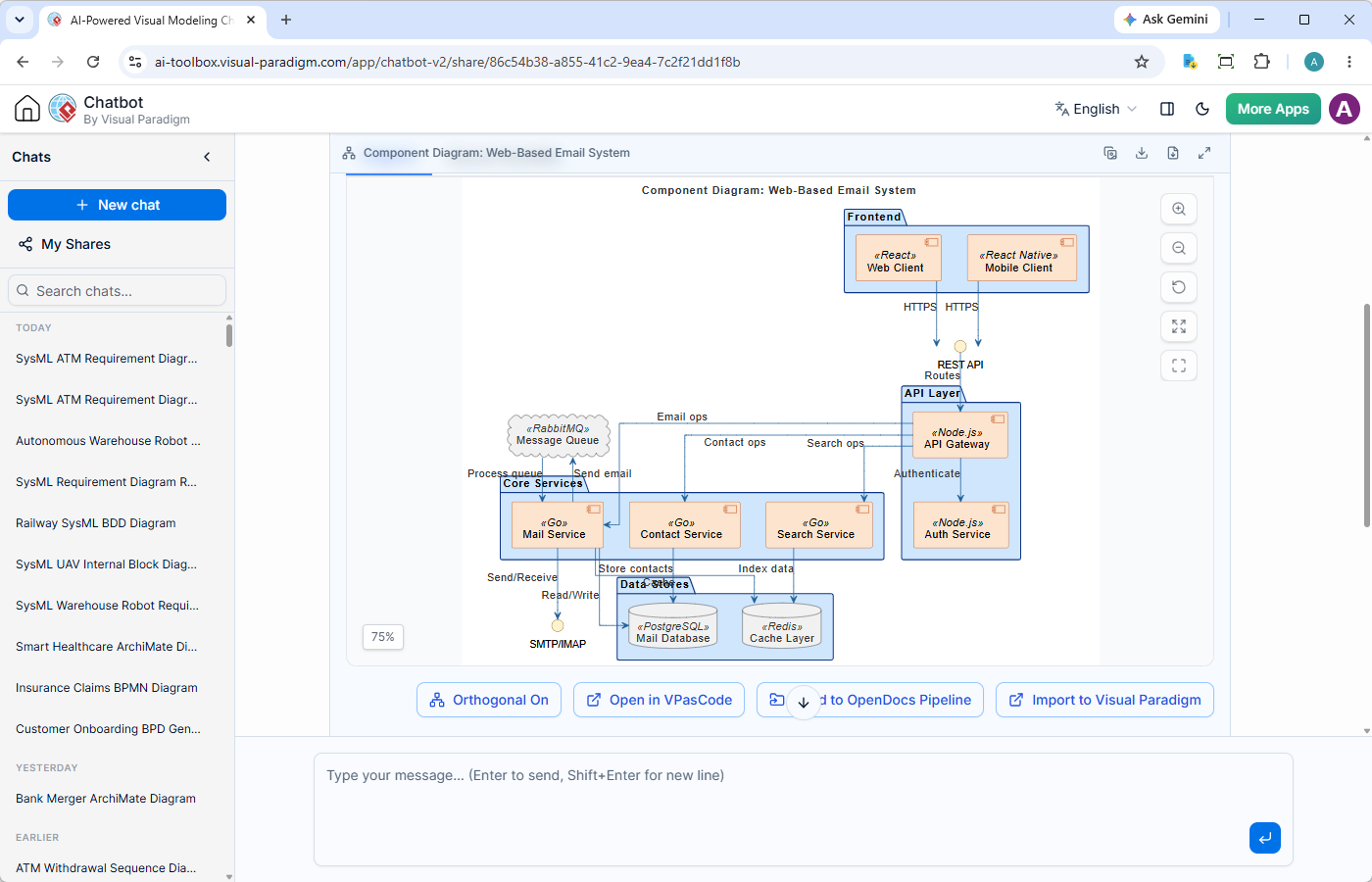
Example AI Prompts for C4-to-UML Translation:
- “Convert my C4 Container definition for the ‘Backend API Gateway’ into a detailed UML Component Diagram showing provided and required interfaces for Auth, Order, and Payment modules.”
- “Refine the generated component diagram to use formal ball-and-socket notation between the Payment Component and the external Stripe API Adapter.”
- “Add explicit ports on the container boundary to represent the inbound REST API and outbound gRPC connections.”
Key Chatbot Advantages for Software Architects:
- High Precision Diagram Engine: Utilizes a specialized AI model trained to produce syntactically correct UML component structures, avoiding invalid connections or broken syntax.
- Conversational Refinement: Adjust abstraction levels, split components, or modify interface dependencies interactively in plain English.
- Multi-Notation Flexibility: Effortlessly switch perspectives. Use the chatbot to generate C4 container models, UML component diagrams, or behavioral flows via built-in AI activity diagram tool capabilities.
- Diagrams-as-Code Output: Generated models produce clean text definitions (PlantUML, Mermaid, Graphviz) that can be easily exported, edited, and version-controlled in Git.
Connecting UML Component Models to the Visual Paradigm Ecosystem
Translating C4 models into formal UML components is integrated directly into Visual Paradigm’s complete software lifecycle platform:
- Document Interface Boundaries in OpenDocs: Export your component diagrams directly to Visual Paradigm OpenDocs to publish clear API boundary guides, service contracts, and interface specifications for development teams.
- Manage Architecture-as-Code via Visual Paradigm VPasCode: Edit textual diagram definitions directly in VPasCode.
- Collaborative Whiteboarding in VP Online: Share persistent chat sessions or export converted models to VP Online for real-time team review and whiteboarding sessions.
- Trace to Implementation in VP Desktop: Import component blueprints into Visual Paradigm Desktop to link architectural components directly to concrete code classes, packages, and database schemas.
Transform Your Architecture Workflow Today
Streamline the transition from high-level C4 container planning to detailed UML component modeling with conversational AI. Try the Visual Paradigm AI Diagramming Chatbot with a free trial today.
Full access is included with both VP Online Deluxe Edition and VP Desktop Professional Edition licenses.
Related Links
- Visual Paradigm VPasCode interactive playground: Try out Visual Paradigm VPasCode in the VPasCode interactive playground
- VPasCode overview: Learn more about VPasCode
- Try the AI Diagramming Chatbot — Generate diagrams from natural-language descriptions and explore how AI can help with your modeling work.
- Explore Solutions & Use Cases — See how the AI Diagramming Chatbot can help you solve real-world modeling and diagramming needs across different industries and use cases.
- Learn More About AI Diagramming Chatbot — Explore the chatbot’s features, capabilities, and how it can support your diagramming workflow.
- Stay Updated on AI Diagramming Chatbot — See the latest features, enhancements, and improvements added to the AI Diagramming Chatbot.