What is SysML
System Modeling Language (SysML) is a modeling language that is used to model complex systems. It is an extension of the Unified Modeling Language (UML), which is commonly used for software development. SysML has been developed to enable engineers to model complex systems in a systematic way, capturing the functional and physical aspects of a system. SysML is a graphical language, based on UML, but it includes new constructs that are specific to systems engineering.
SysML is designed to be used by systems engineers to model complex systems. It is particularly useful for modeling systems that have both software and hardware components, as it enables engineers to model the interactions between these components. The language includes constructs that are specific to systems engineering, such as requirements, constraints, and parametrics. SysML also includes constructs that are common to UML, such as classes, objects, and relationships.
Benefits of SysML
One of the key benefits of SysML is that it provides a common language for engineers to communicate with each other. It enables engineers to model a system using a standard set of constructs, which makes it easier for others to understand the model. This can be particularly useful when working on complex systems with multiple engineers involved.
Another benefit of SysML is that it enables engineers to model both the functional and physical aspects of a system. This is important as many systems have both software and hardware components, and it is important to model how these components interact with each other. SysML provides constructs that enable engineers to model both the logical and physical components of a system, as well as the interactions between these components.
SysML vs UML
SysML is an extension of UML, developed specifically for systems engineering by the Object Management Group (OMG) in collaboration with the International Council on Systems Engineering (INCOSE). It was developed as a profile extension of UML to avoid cluttering the existing language with systems engineering concepts. SysML is treated as a modeling language in its own right, and it adds new model elements that are specific to systems engineering while removing elements that are not useful in this context.
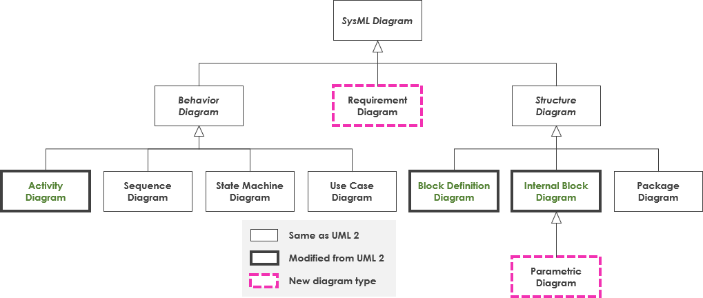
SysML is a smaller language than UML, with only nine different diagram types compared to UML’s fourteen. The SysML diagrams include Block Definition Diagrams (BDDs), Internal Block Diagrams (IBDs), Requirements Diagrams, Parametric Diagrams, Sequence Diagrams, State Machine Diagrams, Activity Diagrams, Use Case Diagrams, and Package Diagrams. These diagram types cover a wide range of systems engineering activities, from defining system components and their relationships to modeling system behavior and requirements.
Nine Types of SysML Diagram
SysML is a powerful modeling language used in Model-Based Systems Engineering (MBSE) applications. It provides a standardized notation and vocabulary for capturing system requirements, structure, behavior, and interactions between system components. SysML diagrams are used to model different aspects of a system, including its physical and functional aspects, requirements, and constraints.
There are nine types of SysML diagrams, each with a specific purpose, and complementary Allocation Tables.
The Three Categories of SysML Diagrams
SysML is a modeling language used for system engineering design and analysis, and it provides a range of diagram types to help model and represent different aspects of a system. SysML diagrams can be broadly divided into three categories: structure diagrams, requirement diagrams, and behavior diagrams.
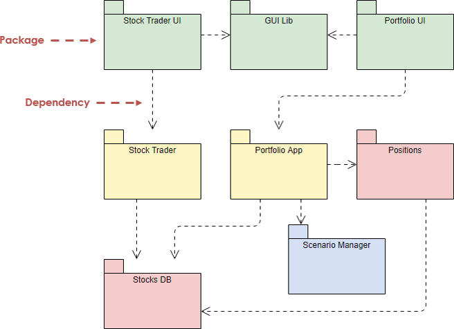
- Structure Diagrams: Structure diagrams are used to represent the physical or logical architecture of a system. The two main types of structure diagrams in SysML are block definition diagrams (BDDs) and internal block diagrams (IBDs). BDDs are used to show the hierarchy and composition of the system’s components, while IBDs show the internal structure of a block and the connections between its parts. The package diagram is another type of structure diagram that shows the organization of the model’s components into packages and their dependencies.
- Requirement Diagram: Requirement diagram is used to define and manage the requirements of a system. The requirements diagram is used to capture and organize the requirements for a system. It helps to define the scope of the system, identify the stakeholders, and trace requirements to specific components or parts of the system.
- Behavior Diagrams: Behavior diagrams are used to represent the dynamic behavior of a system, including its activities, states, and interactions. There are several types of behavior diagrams in SysML, including activity diagrams, state machine diagrams, sequence diagrams, and use case diagrams. Activity diagrams show the flow of activities in a system, state machine diagrams show the behavior of a system in response to events and changes in state, sequence diagrams show the interactions between components or parts of a system, and use case diagrams show the interaction between the system and its users or external entities.
In short, SysML has nine diagram types that are divided into three major categories: structure diagrams, requirement diagrams, and behavior diagrams. These diagrams help to model and represent different aspects of a system, such as its physical and logical architecture, requirements, and dynamic behavior.
Here’s an overview of each diagram type and its purpose:
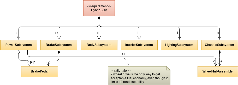
1. Block Definition Diagrams (BDDs): BDDs are used to define the blocks that make up a system and their relationships. Blocks represent the components of a system and their interactions, and can be hierarchical.
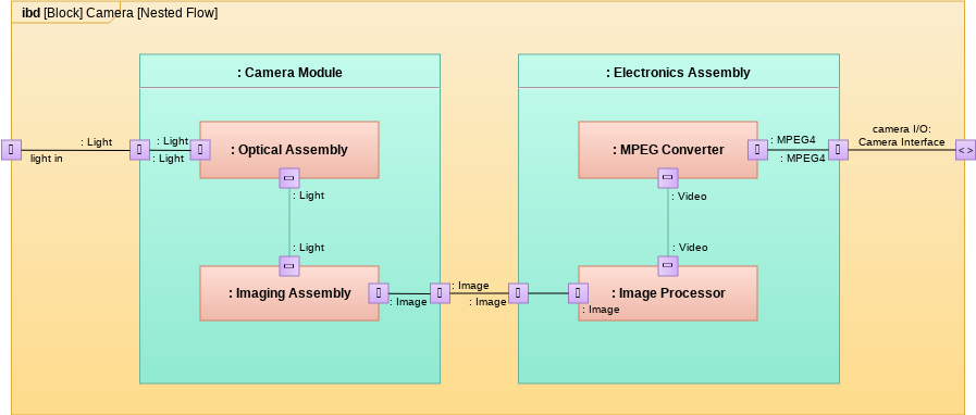
2. Internal Block Diagrams (IBDs): IBDs depict the internal structure of a block, showing the parts that make up the block and their relationships.
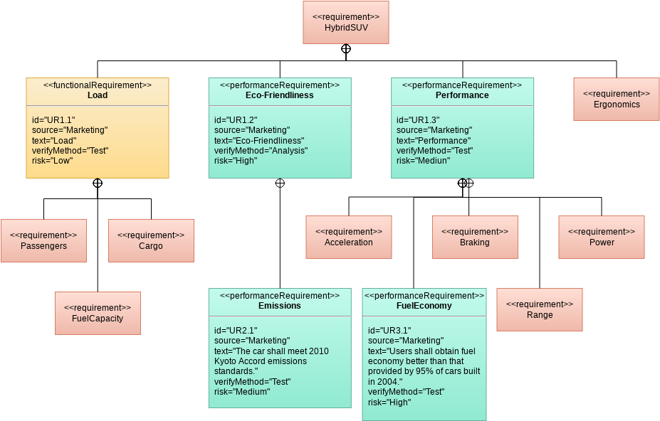
3. Requirements Diagrams: Requirements diagrams are used to capture system requirements, including functional, performance, and interface requirements. They provide a way to track requirements and ensure they are being met.
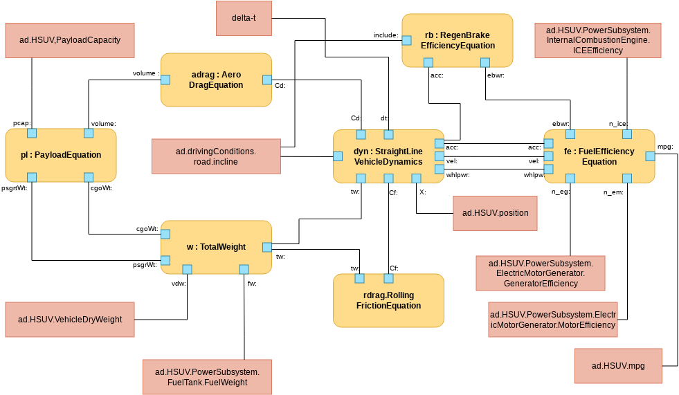
4. Parametric Diagrams: Parametric diagrams are used to model the behavior of a system by showing how the system responds to different inputs and environmental conditions. They show the relationships between system parameters and their values.
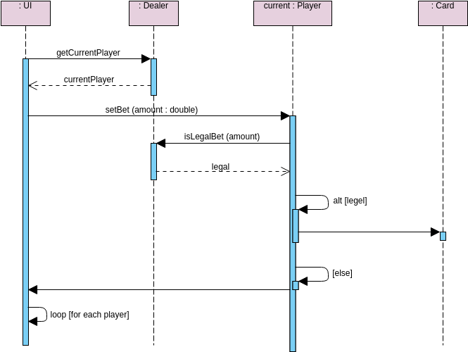
5. Sequence Diagrams: Sequence diagrams are used to model the interactions between system components over time. They show the order of messages between components and can be used to verify system behavior.
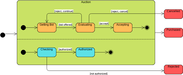
6. State Machine Diagrams: State machine diagrams are used to model the behavior of a system over time, showing the different states a system can be in and how it transitions between states.
7. Activity Diagrams: Activity diagrams are used to model the flow of activities in a system, showing the steps involved in a process and their relationships.
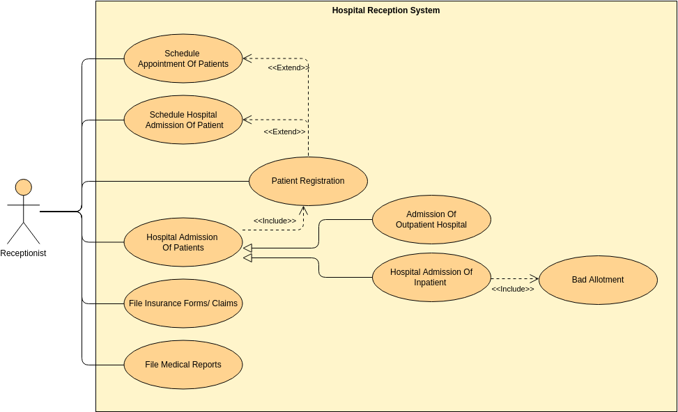
8. Use Case Diagrams: Use case diagrams are used to model the interactions between a system and its users, showing the different use cases and actors involved in a system.
9. Package Diagrams: Package diagrams are used to organize the different elements of a system, including blocks, requirements, and diagrams.
In addition to these diagrams, SysML also includes Allocation Tables, which provide a way to allocate system requirements to specific system components and track their implementation.
Summary
SysML is a modeling language used for model-based systems engineering. It provides a graphical notation for modeling complex systems and supports the specification, analysis, design, verification, and validation of systems. SysML has nine diagram types, including requirement diagrams, use case diagrams, block definition diagrams, internal block diagrams, parametric diagrams, sequence diagrams, state machine diagrams, activity diagrams, and communication diagrams. Additionally, SysML provides Allocation Tables to allocate requirements, functions, and components to each other, ensuring traceability and seamless integration of system components. Overall, SysML is a powerful tool for systems engineers to model complex systems and ensure that all system requirements are met.