


In the realm of software development and system design, understanding and visualizing the architecture of a project is crucial. This is where Unified Modeling Language (UML) comes to the forefront with its array of diagram types, each serving a specific purpose. Among these, the UML Package Diagram stands out as an invaluable tool for depicting the high-level structure of a system or software application. In this article, we will delve into the world of UML Package Diagrams, exploring what they are, how they are used, and why they are essential in software development.
What is a UML Package Diagram?
A UML Package Diagram is a structural diagram that provides a clear and concise representation of the system’s organizational structure. It’s a visual tool used to depict the various packages, sub-packages, and the relationships between them within a system. Think of it as a hierarchical map of your software project, breaking it down into manageable components.
In UML, a package is a general-purpose mechanism to organize elements, such as classes, interfaces, components, and other packages. These packages help in partitioning the system into smaller, more manageable units, allowing for better organization, modularity, and maintenance.
Why Use UML Package Diagrams?
UML Package Diagrams offer several compelling advantages in software development:
- Visualization: They provide a visual representation of the system’s structure, making it easier for developers, architects, and stakeholders to understand the organization of the software.
- Modularity: Packages help in breaking down complex systems into manageable and cohesive modules. This enhances modularity, allowing developers to work on individual packages without affecting the entire system.
- Dependency Management: The arrows representing dependencies between packages assist in identifying relationships and potential bottlenecks in the system. This helps in managing dependencies effectively and avoiding circular dependencies.
- Communication: UML Package Diagrams serve as a powerful communication tool among team members, ensuring everyone is on the same page regarding the system’s architecture.
- Documentation: They provide a visual basis for documenting the system’s structure, which can be invaluable for future maintenance, updates, and knowledge sharing.
Key Elements of a UML Package Diagram
Before we delve deeper into the significance of UML Package Diagrams, let’s explore the key elements that constitute such a diagram:
- Package: The primary element of the diagram, a package, is depicted as a rectangle with a folded-over corner. It represents a container for other elements or sub-packages.
- Package Name: Each package has a name, which is usually placed inside the rectangle.
- Dependencies: Arrows between packages or package contents indicate dependencies between them. These can be used to illustrate which parts of the system rely on others.
- Elements: Inside each package, you can include various elements like classes, interfaces, and other UML diagram elements to represent the components or modules of the system.
- Visibility Symbols: Packages may have visibility symbols (e.g., + for public, – for private) next to their names to denote the access level of their contents.
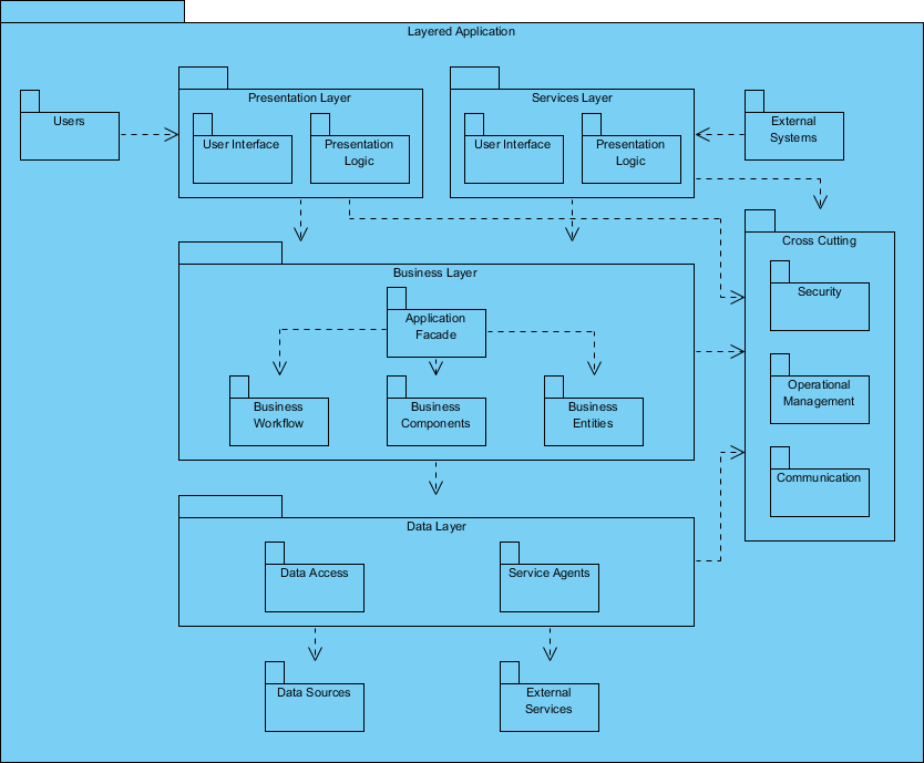
Package Diagram Example
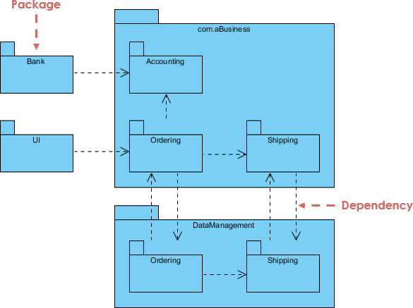
Key Concepts of Package Diagram
In UML Package Diagrams, the emphasis is on organizing and structuring the system’s components into manageable and meaningful packages. These diagrams help software architects and developers to visualize, document, and communicate the architectural aspects of a software system, facilitating better understanding and management of dependencies and modularity.
Let’s break down these concepts and constraints for a clearer understanding:
- Hierarchical Structure of Nested Packages: UML Package Diagrams follow a hierarchical structure, where packages can contain other packages, creating a nesting effect. This hierarchical organization helps in structuring and organizing components and modules within a system.
- Atomic Modules for Nested Packages are usually Class Diagrams: In many cases, the atomic modules or elements contained within nested packages are class diagrams. Class diagrams are a common choice to represent the detailed structure of a package’s contents, including classes, interfaces, and their relationships.
- Constraints while Using Package Diagrams:
- Unique Package Names: Each package within a system should have a unique name. This ensures clarity and avoids ambiguity in identifying different parts of the system.
- Classes with the Same Name: Classes inside different packages can have the same name without conflicts. The package context distinguishes them.
- Variability in Package Content: Packages can vary in terms of what they include. They can contain whole diagrams (such as class diagrams), the names of components (e.g., classes, interfaces), or even no components at all, serving as a purely organizational container.
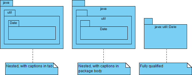
- Fully Qualified Name of a Package: A fully qualified name of a package is a way to uniquely identify it within the context of the system. The syntax for a fully qualified package name typically follows a hierarchical structure, using dots (.) to separate nested packages. For example, if you have a package structure like “System -> Subsystem -> Component,” the fully qualified name might be “System.Subsystem.Component.”
- Representation of Packages: Packages in UML Package Diagrams can be represented using notations that visually depict them. These notations often involve rectangular shapes with tabs at the top to display the package name. Additionally, dependencies between packages can be represented using arrows, typically with dotted lines, to illustrate how one package depends on another.
Representing Dependencies between Packages
Overall, UML Package Diagrams play a crucial role in software architecture by providing a high-level view of the organization and dependencies between packages, which is essential for effective system design, communication, and documentation.
For example, the use of stereotypes like <<import>> and <<access>> adds clarity and specificity to the types of dependencies being depicted, enhancing the diagram’s comprehensibility.
Let’s expand on these concepts:
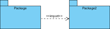
- <<import>> Dependency:
- Meaning: In UML Package Diagrams, a <<import>> dependency signifies that one package imports the functionality or elements of another package. This allows the importing package to use or access elements from the imported package without necessarily including them physically.
- Representation: This dependency can be represented using the <<import>> stereotype, typically displayed above the dependency arrow between the two packages involved.
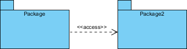
- <<access>> Dependency:
- Meaning: The <<access>> dependency indicates that one package requires the assistance or services provided by the functions or elements of another package. It implies a runtime or execution-level dependency between the two packages.
- Representation: Similar to <<import>>, the <<access>> dependency can be represented with the <<access>> stereotype placed above the dependency arrow between the packages.
- Custom Stereotypes:
- While <<import>> and <<access>> are commonly used stereotypes to represent dependencies in package diagrams, UML allows users to define their own custom stereotypes to represent specific types of dependencies. This flexibility allows you to tailor your diagrams to accurately depict the relationships between packages in your system.
Modeling Complex Grouping:
-
- Package diagrams are indeed ideal for modeling complex grouping and hierarchical relationships between packages and other objects in a system. They help to create a visual representation of the organization and structure of a software system, making it easier for stakeholders to understand how components are grouped and how they interact.
How to Create a UML Package Diagram
Creating a UML Package Diagram involves the following steps:
- Identify Packages: Determine the main packages and sub-packages in your system. Think about how you want to organize your components logically.
- Define Relationships: Establish dependencies between packages using arrows. Use solid lines for strong dependencies and dashed lines for weaker ones.
- Add Elements: Populate the packages with classes, interfaces, or other relevant UML elements. Connect these elements to the packages to illustrate their membership.
- Include Visibility Symbols: If necessary, add visibility symbols to denote the access level of package contents.
- Label Packages: Label each package with a meaningful name that reflects its purpose within the system.
- Review and Refine: Review the diagram for accuracy and clarity. Refine it as needed to ensure it effectively communicates the system’s architecture.
Conclusion
UML Package Diagrams are a vital tool for understanding, documenting, and communicating the architecture of software systems. They enable developers and architects to break down complex systems into manageable packages, visualize dependencies, and ensure clear communication among team members. By utilizing UML Package Diagrams, software projects can benefit from improved organization, modularity, and maintainability, ultimately leading to more successful and efficient development processes. So, the next time you embark on a software development journey, consider unveiling the architecture with the power of UML Package Diagrams.