

Generating a Use Case Diagram with AI
Visual Paradigm’s AI Diagram Generation feature can create a solid starting point for your use case diagram in seconds, saving significant time during early modeling.
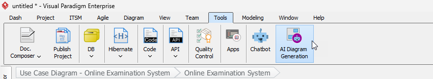
- Select Tools > AI Diagram Generation from the main menu.
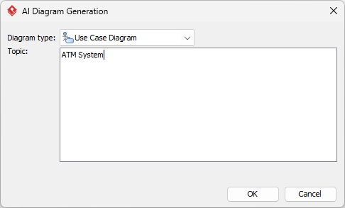
- In the AI Diagram Generation window, choose Use Case Diagram as the diagram type. Enter a clear description of your project, system, or problem in the Topic field, then click OK.
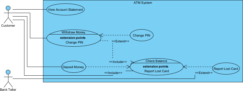
- The AI analyzes your description and automatically generates a complete use case diagram tailored to your input.
- Refine the generated diagram by editing names, adding or removing elements, adjusting layout, applying colors, or adding more shapes and relationships. Diagram editing tools are covered in more detail in the next section.
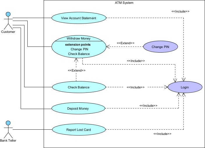
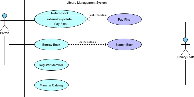
Use case diagram generated by AI, with manual editing
Drawing a Use Case Diagram Manually
While AI generation is fast and convenient, manual creation gives you full control over every detail. In this section, we will build a use case diagram for a simple Library Management System from scratch.
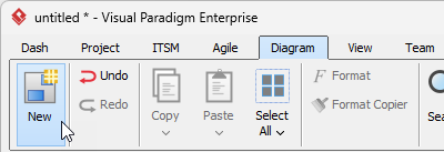
- Select Diagram > New from the main menu.
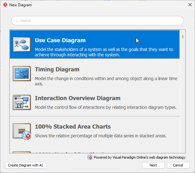
- Select Use Case Diagram and click Next.
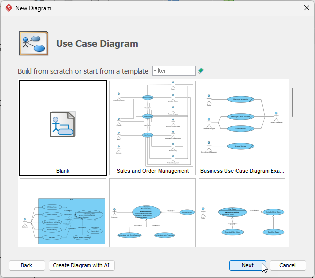
- Choose Blank to start with an empty canvas, then click Next.
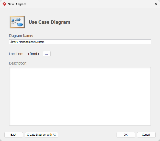
- Enter a meaningful name for the diagram (e.g., “Library Management – Use Cases”) and click OK.
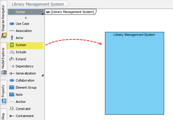
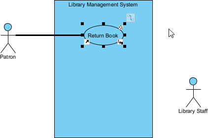
- Create the system boundary first. In the diagram toolbar (left side), click System, then click and drag on the canvas to draw the rectangle. Name it Library Management System.
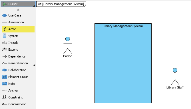
- Add the two main actors: Patron (primary actor) on the left and Library Staff (secondary actor) on the right — this is a common convention for readability.
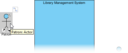
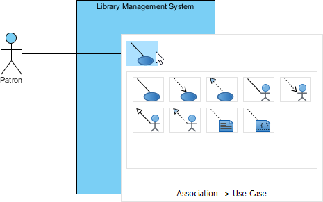
- Now create use cases connected directly to actors. Hover over the Patron actor until the Resource Catalog icon appears.
- Press and drag the Resource Catalog icon into the system boundary.
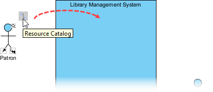
- Release the mouse and choose Association → Use Case from the popup.
- Name the new use case Return Book.
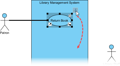
- Next, model the exceptional case of paying a fine. Hover over the Return Book use case, drag from the Resource Catalog downward, and select Extend → Use Case.
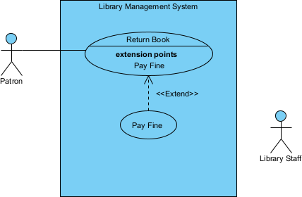
- Name the extending use case Pay Fine. Your diagram should now resemble this:
- Use the same Resource Catalog technique to complete the diagram with the remaining elements:
- Actors: Patron, Library Staff
- Base use cases: Return Book, Borrow Book, Register Member, Manage Catalog
- Extend relationship: Return Book ← extend ← Pay Fine
- Include relationship: Borrow Book → include → Search Book
Documenting Flow of Events and Scenarios
After creating the diagram, document the detailed Flow of Events (main success scenario + alternatives/exceptions) to clearly specify behavior and validate requirements with stakeholders.
- Right-click the desired use case (e.g., Borrow Book) and select Open Use Case Details… from the context menu.
- In the Use Case Details window, switch to the Flow of Events tab.
- Enter the main success scenario as a numbered list of steps:
1. The Patron uses the Search Book feature to locate the desired book. 2. The Patron selects a book from the search results. 3. The system checks the availability of the selected book. 4. The Patron requests to borrow the book. 5. The system validates the Patron’s membership status and borrowing privileges. 6. The system records the borrowing transaction. 7. The system assigns a due date to the borrowed book. 8. The system confirms successful borrowing to the Patron (e.g., via message or receipt). 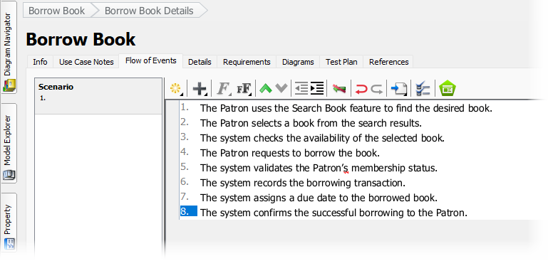
Note: You can create additional scenarios (alternative flows, exceptions, etc.) in the left pane to document different paths under the same use case.
With the diagram structure and detailed flows in place, you now have a clear, validated foundation for requirements — ready to drive design, development, and testing in an agile manner.