


Introduction
Class Diagrams and Entity-Relationship Diagrams (ERDs) are two essential tools in software and database design. While they share some similarities, they serve different purposes and are used in different contexts. In this article, we’ll explore the differences between these two diagram types, provide examples, and discuss when to use each.
Class Diagram
Purpose:
A class diagram is primarily used in object-oriented programming and design to represent the structure and relationships of classes and objects within a system. It is a fundamental part of Unified Modeling Language (UML) and helps visualize the system’s static structure.
Elements:
- Class: Represents a blueprint for an object, defining its attributes (data members) and methods (functions).
- Association: Depicts relationships between classes, including one-to-one, one-to-many, and many-to-many associations.
- Inheritance: Illustrates the inheritance hierarchy, indicating which classes inherit from others.
- Aggregation and Composition: Represents relationships between whole-part entities, such as a car and its engine.
- Attributes and Operations: Show the properties (attributes) and behaviors (methods) of a class.
Example:
Let’s consider a simplified example for representing a library system using class diagrams:
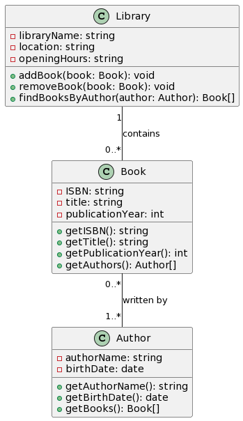
In this class diagram, we have classes like Library, Book, and Author, showing their attributes and associations.
Entity-Relationship Diagram (ERD)
Purpose:
An ERD is primarily used in database design to represent the structure and relationships of entities (tables) within a database. It focuses on capturing the data model, including entities, attributes, and relationships.
Elements:
- Entity: Represents a table in a relational database, often corresponding to real-world objects or concepts.
- Attributes: Depict the properties or fields of an entity.
- Relationships: Illustrate how entities are related, including one-to-one, one-to-many, and many-to-many relationships.
- Primary Key: Identifies a unique attribute or combination of attributes that uniquely identifies each entity instance.
- Foreign Key: Represents a link between entities and enforces referential integrity in the database.
Example:
Let’s consider an ERD for a simplified e-commerce system:
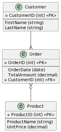
In this ERD, we have entities like Customer, Order, and Product, along with their attributes and relationships. The foreign keys (CustomerID, ProductID) establish the connections between these entities.
When to Use Which?
Use Class Diagram When:
- Designing Object-Oriented Systems: If you are working on an object-oriented software project and need to represent classes, objects, and their relationships, use class diagrams.
- Modeling Software Architecture: Class diagrams are useful for visualizing the static structure of software systems, including class hierarchies, interfaces, and dependencies.
- Collaborative Design: Class diagrams are often employed in collaborative design sessions to facilitate discussions among developers, designers, and stakeholders.
Use Entity-Relationship Diagram When:
- Database Design: When designing a relational database, use ERDs to define tables, their attributes, and relationships between them.
- Data Modeling: ERDs are essential for modeling and understanding data requirements, ensuring data integrity, and organizing database schemas.
- Database Documentation: ERDs serve as valuable documentation for database administrators and developers, describing the database’s structure and constraints.
Summarizing the Differences between Class Diagram and ERD
Here’s a table contrasting the differences between Class Diagrams and Entity-Relationship Diagrams (ERDs) in various aspects:
| Aspect | Class Diagram | Entity-Relationship Diagram (ERD) |
|---|---|---|
| Purpose | Represents classes, objects, and their relationships in object-oriented design and software architecture. | Represents entities, attributes, and relationships in database design and data modeling. |
| Primary Use Cases | – Object-oriented software design<br>- Modeling software architecture | – Relational database design<br>- Data modeling |
| Elements | – Classes<br>- Attributes<br>- Methods (Operations)<br>- Associations<br>- Inheritance<br>- Aggregation/Composition | – Entities (Tables)<br>- Attributes (Columns)<br>- Relationships<br>- Primary Keys<br>- Foreign Keys |
| Cardinalities | Used for showing associations between objects or classes. Can represent multiplicity (e.g., one-to-one, one-to-many). | Used for showing relationships between entities in a database (e.g., one-to-one, one-to-many). |
| Notation | – Classes with compartments for attributes and methods<br>- Lines with arrows to represent associations | – Rectangles for entities (tables)<br>- Diamonds for relationships<br>- Ovals for attributes |
| Focus | Focuses on the static structure of software systems. | Focuses on capturing the data model, emphasizing data and relationships. |
| Dependency on Programming Paradigm | Closely tied to object-oriented programming paradigms. | Independent of programming paradigms; used for databases in various programming languages. |
| Use in Software Development | Commonly used for object-oriented software development, UML-based modeling. | Essential for database design, schema development, and ensuring data integrity. |
| Collaborative Design | Facilitates collaborative design discussions among developers and stakeholders. | Helps database administrators and developers create and document database schemas. |
| Extensibility | Extensible to incorporate software design patterns, interfaces, and architectural concepts. | Less extensible for representing non-database-related software design patterns.
|
This table provides a clear comparison of the two diagram types in various aspects, highlighting their primary uses, elements, notations, and roles in different phases of software development and data modeling. The choice between class diagrams and ERDs depends on the specific needs of the project and the focus of design and modeling activities.
Summary
The article explores the key differences between Class Diagrams and Entity-Relationship Diagrams (ERDs), two essential tools in software and database design. Class Diagrams, primarily used in object-oriented programming, focus on visualizing the structure and relationships of classes and objects within a system. On the other hand, ERDs are vital for database design, representing entities, attributes, and relationships in a relational database.
Class Diagrams emphasize the static structure of software systems, featuring classes, attributes, methods, and associations, making them ideal for object-oriented software design and architectural modeling. They are highly extensible and foster collaborative design discussions.
ERDs, in contrast, center around data modeling, capturing the structure of a database, including tables, columns, relationships, and constraints. ERDs are indispensable for ensuring data integrity and organizing database schemas. They are not bound to any specific programming paradigm and are used in various programming languages.
The choice between Class Diagrams and ERDs depends on the project’s focus and requirements. Class Diagrams suit object-oriented software development and architectural modeling, while ERDs are essential for database design and data modeling tasks. Both diagram types play crucial roles in different phases of software development and design, enhancing the understanding and communication of complex systems and data models.