


Component diagrams and deployment diagrams are two types of diagrams used in the Unified Modeling Language (UML) to model different aspects of a software system. They serve different purposes and focus on different aspects of system design and implementation.
-
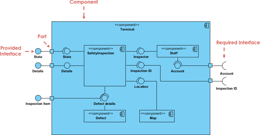
Component Diagram
- Purpose: Component diagrams are primarily used to represent the high-level structure of a software system in terms of its components and their relationships. They focus on the organization and modularization of the software system.
- Elements: Component diagrams include components, interfaces, connectors, and dependencies.
- Components: These represent the major building blocks or modules of the system. They can be physical or logical entities, such as classes, packages, or even entire subsystems.
- Interfaces: These define the contracts or APIs that components expose to interact with each other.
- Connectors: Connectors show how components interact or communicate with each other. Examples include associations, dependencies, and aggregations.
- Use Cases: Component diagrams are used during the design phase to illustrate the system’s architecture, the relationships between components, and their interfaces. They help in understanding the system’s structure and how it’s organized.
Deployment Diagram
-
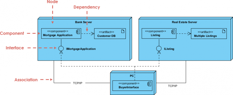
- Purpose: Deployment diagrams focus on the physical deployment of software components and their relationships to hardware and other software elements. They are used to model the system’s deployment architecture, including servers, nodes, and communication pathways.
- Elements: Deployment diagrams include nodes, artifacts, and associations.
- Nodes: These represent hardware or software processing elements, such as servers, workstations, or even devices like routers or printers.
- Artifacts: Artifacts are the actual software components or files deployed on nodes, such as executable files, libraries, or databases.
- Associations: Associations show the relationships between nodes and artifacts, indicating which components are deployed on which nodes.
- Use Cases: Deployment diagrams are typically used during the implementation phase and system deployment. They help in planning and visualizing how software components are distributed across the physical infrastructure, including servers, networks, and other resources.
Component vs Deployment Diagram
This following table highlights the key differences and purposes of component diagrams and deployment diagrams in UML. Component diagrams focus on the logical structure and organization of software components, while deployment diagrams focus on the physical deployment of those components on hardware nodes.
| Aspect | Component Diagram | Deployment Diagram |
|---|---|---|
| Purpose | Represent the high-level software structure | Model the physical deployment of software components |
| Focus | Logical organization and relationships of components | Physical deployment on hardware and nodes |
| Main Elements | – Components (e.g., classes, packages, subsystems) | – Nodes (e.g., servers, workstations) |
| – Interfaces (e.g., contracts, APIs) | – Artifacts (e.g., files, databases) | |
| – Connectors (e.g., associations, dependencies) | – Associations (indicating deployment relationships) | |
| Use Cases | – Design phase: System architecture and structure | – Implementation phase: Deployment planning |
| – Illustrate component relationships and interfaces | – Visualize component distribution on hardware | |
| Abstraction Level | High-level abstraction | Low-level abstraction |
| Notation | Components, interfaces, connectors | Nodes, artifacts, associations |
| Relationships Represented | Dependencies, associations, aggregations, etc. | Deployment associations, mapping of components to nodes |
| Example Scenario | Representing software modules and their | Visualizing how web server software |
| interactions in a banking application | components are deployed on physical servers |
Summary
Component diagrams focus on the high-level structure and organization of software components within a system, while deployment diagrams concentrate on how these components are physically deployed on hardware or nodes. Both types of diagrams are valuable for different stages of software development and provide different perspectives on system design and architecture.