


Introduction to the 14 kinds of UML diagrams and the conceptual building blocks
Things, Relationships, and Diagrams.
UML 2.5 (Unified Modeling Language version 2.5, formalized by the Object Management Group in 2015 with minor updates in 2.5.1) is the standardized visual modeling language for specifying, visualizing, constructing, and documenting the artifacts of software systems—and increasingly, business processes, hardware/software integrations, and more. It provides a common “vocabulary” that bridges developers, architects, analysts, testers, stakeholders, and even AI-assisted tools.
At its foundation, every UML diagram is built from three conceptual building blocks:
- Things — The basic elements or “nouns” of the model. These represent conceptual or physical entities in the system.
- Examples: Class (a template for objects with attributes and operations), Actor (external entity interacting with the system, like “Customer” or “Payment Gateway”), Use Case (a goal-oriented functionality, e.g., “Place Order”), Object (a specific instance at runtime), Node (physical/hardware element like a server), Component (modular, replaceable part like a microservice), State (a condition during an object’s lifecycle), Activity (a step in a workflow), etc.
- Relationships — The “verbs” or connections that link things, expressing how elements interact, depend on, or inherit from each other.
- Common examples: Association (structural link, e.g., “Customer places Order”), Generalization (inheritance, “PremiumCustomer is-a Customer”), Dependency (one element relies on another, often temporary), Realization (implementation of an interface/contract), Aggregation/Composition (whole-part relationships, e.g., “Car has Engine”), Include/Extend (use case reuse), Message (interaction flow in behavioral diagrams).
- Diagrams — The graphical views or “lenses” that organize selected things and relationships to communicate a specific perspective of the system. Diagrams are not the model itself—the model is the underlying semantic repository (the “semantic backplane” in tools like Visual Paradigm)—but rather selective visualizations of it.
UML 2.5 defines exactly 14 diagram types, divided into two main categories:
- Structural Diagrams (7) — Focus on the static architecture: what the system is made of, its parts, and how they are organized (snapshot of structure, independent of time).
- Behavioral Diagrams (7) — Focus on the dynamic behavior: how the system works over time, interactions, workflows, state changes, and responses to events.
Structural Diagrams (Static Views)
- Class Diagram — Shows classes, interfaces, attributes, operations, and relationships (most widely used for domain modeling and code generation).
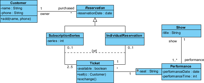
- Object Diagram — Snapshot of instances (objects) and links at a specific moment (useful for debugging or illustrating examples).
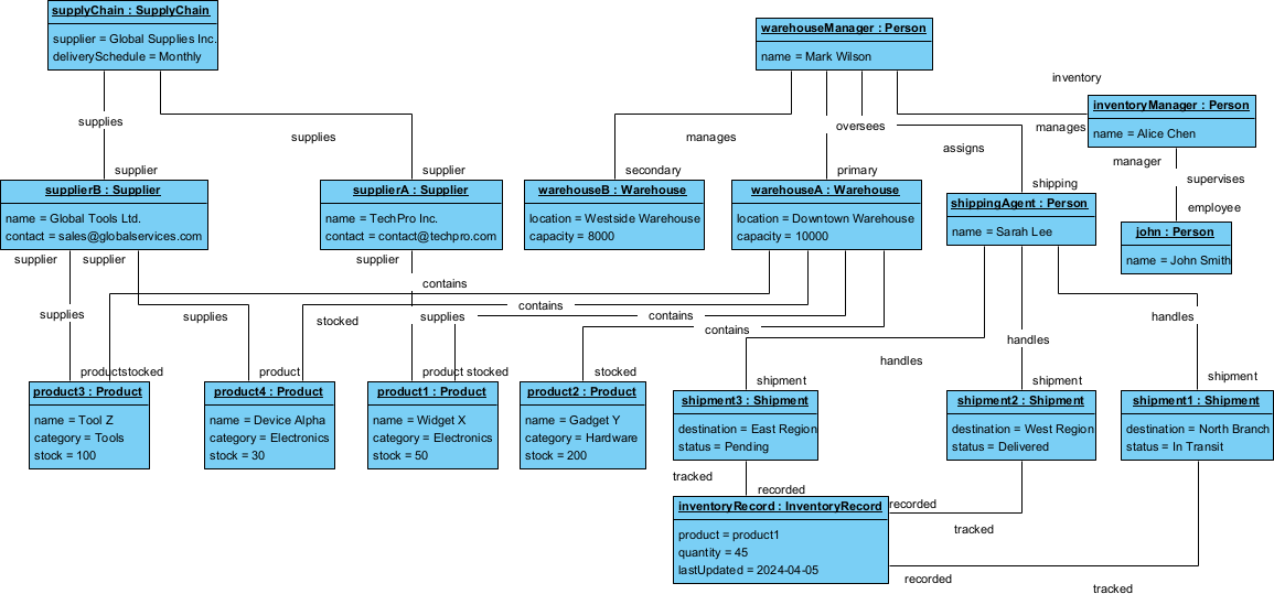
Warehouse Management System object diagram - Package Diagram — Organizes elements into hierarchical namespaces (like folders for large models, dependency management).
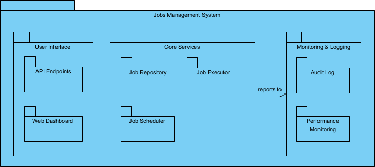
Jobs management system Package Diagram - Component Diagram — Shows software components (modules, libraries, services), interfaces, and dependencies (great for modular/microservices design).
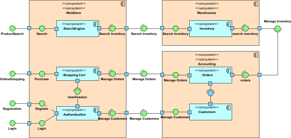
Web store UML component diagram - Composite Structure Diagram — Internal structure of a class or collaboration, with parts, ports, and connectors (ideal for complex objects like subsystems).
- Deployment Diagram — Maps software artifacts to hardware nodes and communication paths (deployment topology, cloud/on-prem planning).
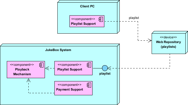
Juke box UML deployment diagram example - Profile Diagram — Defines custom extensions (stereotypes, tagged values, constraints) to tailor UML for domains like Agile, enterprise architecture, or safety-critical systems.
Behavioral Diagrams (Dynamic Views)
- Use Case Diagram — High-level overview of system functionality from external actors’ perspectives (requirements capture).
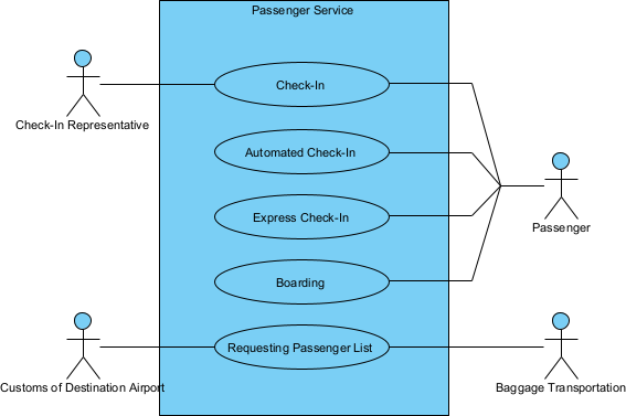
Passenger service UML use case diagram - Activity Diagram — Workflow and business processes with control/data flows, swimlanes, decisions, forks (like enhanced flowcharts).
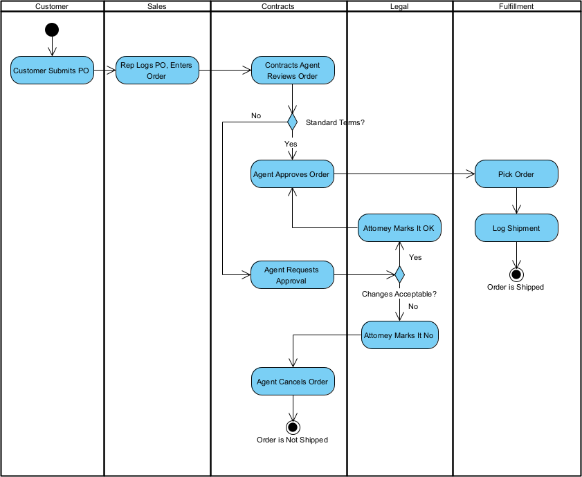
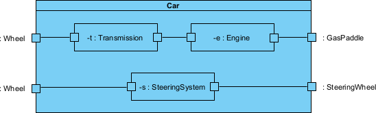
Order fulfillment UML activity diagram - State Machine Diagram (or Statechart) — Lifecycle and event-driven behavior of objects (states, transitions, guards, actions).
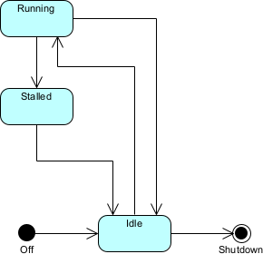
Car engine UML state diagram example - Sequence Diagram — Time-ordered interactions via messages between participants (focus on chronology, most common for interaction details).
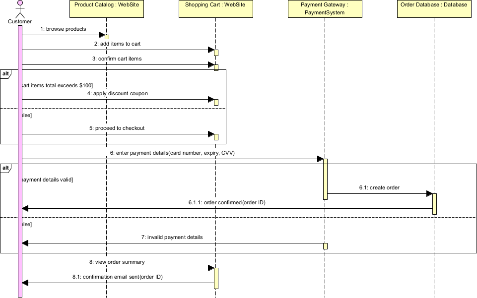
Shipping cart checkout sequence diagram example - Communication Diagram (formerly Collaboration) — Interactions emphasizing structural links over time (message numbering shows sequence).
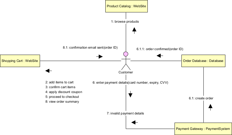
Shipping cart checkout communication diagram example - Interaction Overview Diagram — High-level control flow mixing activity diagram notation with references to detailed interactions (big-picture orchestration).
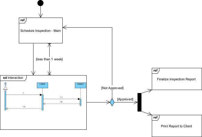
Inspection UML interaction overview diagram example - Timing Diagram — Precise timing constraints, state changes, and durations over a linear timeline (critical for real-time/performance systems).
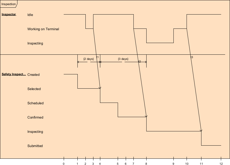
Inspection UML timing diagram example
Practical examples across projects illustrate how these building blocks and diagrams come to life:
- E-commerce platform
- Things: Class “Order”, Actor “Customer”, Use Case “Checkout”.
- Relationships: Association (Customer → Order), Generalization (GuestCheckout extends Checkout).
- Diagrams used: Use Case Diagram (scope features), Class Diagram (domain model with Order, CartItem, Payment), Sequence Diagram (payment flow: Customer → Cart → Gateway → Bank), Deployment Diagram (frontend app on cloud nodes, backend services on separate servers).
- Mobile banking app
- Things: Actor “User”, Component “AuthService”, Node “Mobile Device”.
- Relationships: Dependency (App depends on Auth API), Realization (SecureToken implements IToken).
- Diagrams: Activity Diagram (login workflow with swimlanes), State Machine Diagram (Account states: Active, Locked, Dormant), Timing Diagram (session timeout constraints), Component Diagram (microservices boundaries).
- IoT smart home system
- Things: Composite part “Thermostat” inside “HomeHub”, State “Heating”.
- Relationships: Composition (Hub has Sensors), Message flows.
- Diagrams: Composite Structure Diagram (internal parts/ports of Hub), Communication Diagram (sensor → hub → cloud), Profile Diagram (custom «IoTDevice» stereotype with tagged values like batteryLevel).
- Legacy modernization project
- Things: Package “LegacyMonolith”, Object instances from runtime snapshot.
- Relationships: Package dependencies to break coupling.
- Diagrams: Package Diagram (refactoring boundaries), Object Diagram (example runtime data), Reverse-engineered Class Diagram (from code to understand structure).
- Real-time trading platform
- Things: Timing constraint “OrderMatch < 5ms”.
- Relationships: Messages with strict timing.
- Diagrams: Timing Diagram (order arrival to execution timeline), Sequence Diagram (high-frequency interactions), Interaction Overview Diagram (overall trade lifecycle orchestration).
- Agile team using Visual Paradigm
- All diagrams share the semantic backplane: Change a Class in the Class Diagram → it auto-updates in Sequence, Component, and Deployment views.
- Profile Diagram creates «UserStory» stereotype for Agile integration.
- Quick sketches (e.g., whiteboard-style Use Case + Activity) attack risks early without heavy commitment.
UML 2.5 emphasizes flexibility: you don’t need all 14 diagrams – pick the few that address your current purpose (per Agile Modeling principles). In Visual Paradigm, the semantic backplane ensures consistency: one underlying model, many views. This overview equips you to select the right diagram for the job as we move into use-case-driven modeling in Module 2.