

Visualizing the physical implementation and logical organization of software units like executables, libraries, microservices, and modules
Component diagrams in UML 2.5 focus on the modular, replaceable building blocks of a software system—showing how larger pieces of implementation (executables, libraries, frameworks, services, subsystems) are structured, connected, and depend on each other. They bridge the logical design (classes, packages) and the physical deployment, emphasizing modularity, interfaces, provided/required services, and reusability.
Key elements:
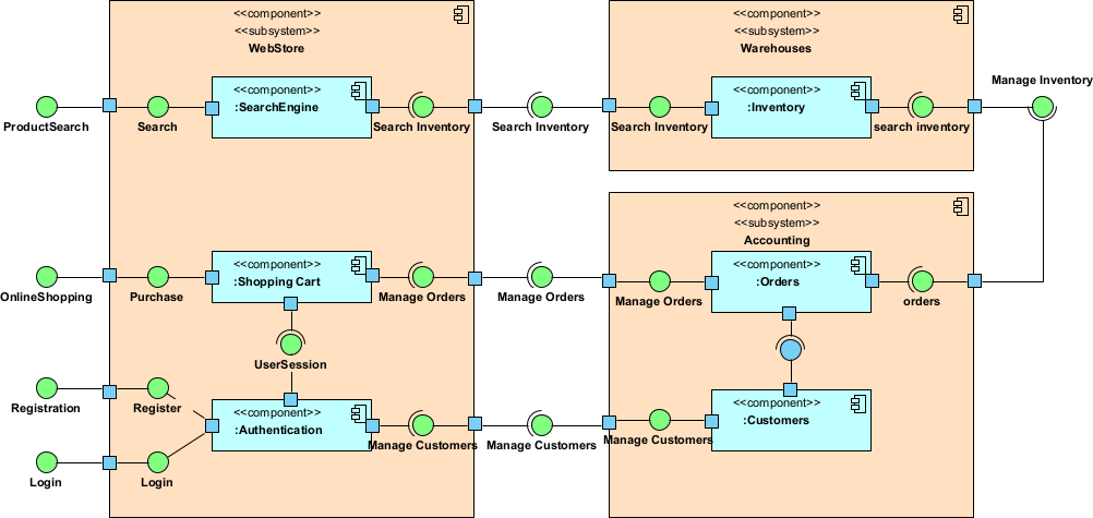
- Component — A rectangle with a small icon in the upper-right corner (two small rectangles), representing a modular unit (e.g., JAR, DLL, microservice, executable, database schema, web service).
- Provided Interface — Lollipop notation (circle on a line) — what the component offers to others (API/contract).
- Required Interface — Socket notation (cup/half-circle) — what the component needs from others to function.
- Dependency — Dashed arrow with open head — one component depends on another (usually via required interface).
- Assembly Connector — Line connecting provided and required interfaces — explicit wiring between components.
- Delegation Connector — Shows internal realization (a component delegates to sub-components).
In Agile & use-case-driven projects, component diagrams are used to:
- Visualize modular architecture (monolith vs. microservices vs. modular monolith)
- Define clear service boundaries and contracts early
- Support incremental development by identifying independently deployable/releaseable units
- Guide refactoring, extract services, or migrate legacy code
- Align implementation with use cases (components realize groups of use cases)
- Facilitate communication between architects, developers, DevOps, and stakeholders
Practical Examples of Component Diagrams in Real Projects
Here are many concrete examples across different architectures and domains:
- E-commerce Platform (Microservices Architecture) Components:
- CatalogService (provides ProductCatalog API)
- CartService (requires ProductCatalog, provides ShoppingCart API)
- OrderService (requires ShoppingCart, ProductCatalog, provides OrderProcessing API)
- PaymentService (requires OrderProcessing, provides PaymentGatewayAdapter)
- InventoryService (provides StockLevel API) Assembly connectors: CartService → CatalogService (uses product info), OrderService → InventoryService (reserves stock). Practical benefit: Clearly shows bounded contexts; helps team decide which services can be scaled independently during peak sales.
- Mobile Banking App (Modular Monolith + External Integrations) Components:
- MobileApp (executable, requires AuthService, TransactionService)
- AuthService (provides Authentication API, uses JWT library)
- TransactionService (provides TransferFunds API, requires CoreBankingAdapter)
- NotificationService (provides PushNotification API)
- CoreBankingAdapter (required interface to legacy mainframe via SOAP)
- FraudDetectionService (external SaaS, required interface) Outcome: Visualizes internal layering + external dependencies; prevents direct coupling from MobileApp to legacy systems.
- Healthcare Integration Platform (Middleware / ESB Style) Components:
- PatientPortal (web app, requires PatientService)
- PatientService (provides HL7 FHIR API)
- EHRAdapter (connects to Epic/Cerner via FHIR)
- AppointmentScheduler (provides Scheduling API)
- BillingGateway (required interface to insurance clearinghouse)
- AuditLoggingComponent (cross-cutting, used by all) Practical: Shows how adapters isolate external systems; supports incremental addition of new hospital system integrations.
- Task Management SaaS (Backend Microservices + Frontend) Components:
- WebFrontend (SPA, requires TaskAPI, CollaborationAPI)
- TaskService (provides CRUD for Boards/Lists/Cards)
- CollaborationService (real-time WebSocket, requires TaskService)
- NotificationService (email/push, requires CollaborationService)
- AuthService (OAuth2/OpenID provider) Connectors: CollaborationService assembles with TaskService via required TaskEvents interface. Benefit: Guides API gateway design and real-time vs. REST separation.
- Legacy ERP Monolith Refactoring (Strangler Fig Pattern) Components (before):
- MonolithicERP (large component containing everything) After incremental extraction:
- NewOrderManagement (microservice, provides OrderAPI)
- LegacyERPWrapper (adapts old monolith, required by new services)
- SharedDomainLibrary (common entities, used by both)
- NewReportingService (extracted, requires OrderAPI) Practical: Component diagram tracks progress of strangler migration—shows shrinking legacy footprint over releases.
- IoT Device Management Platform Components:
- DeviceGateway (handles MQTT/HTTP ingestion, provides DeviceTelemetry API)
- RulesEngine (processes events, requires DeviceTelemetry)
- AnalyticsService (provides Dashboard API)
- FirmwareUpdateService (provides OTA updates)
- DeviceRegistry (provides DeviceMetadata API) Connectors: RulesEngine → DeviceGateway (required), FirmwareUpdateService → DeviceRegistry. Outcome: Clarifies edge-to-cloud responsibilities; supports adding new device protocols via pluggable gateways.
- Restaurant POS & Online Ordering System Components:
- POSClient (desktop app at restaurant, requires OrderProcessing)
- OnlineOrderingService (web/mobile, provides CustomerOrder API)
- KitchenDisplaySystem (requires OrderProcessing)
- PaymentTerminalAdapter (hardware integration)
- CentralOrderService (core business logic) Practical: Shows how in-store and online channels converge on shared order processing without duplication.
- Agile Team Using Visual Paradigm
- Start with high-level component diagram in early sprints (major subsystems realizing use case groups).
- Refine with provided/required interfaces as APIs solidify.
- Use stereotypes: «microservice», «library», «executable», «database», «external».
- Semantic backplane ensures component interfaces link to class/sequence diagrams.
- Generate component-based code skeletons or reverse-engineer from existing modules.
Common patterns visible in component diagrams:
- Layered architecture (presentation → application → domain → infrastructure)
- Hexagonal/Ports & Adapters (core domain isolated from external tech)
- Microservices with API contracts
- Legacy wrapping and gradual extraction
Component diagrams answer: “How is the software physically/modularly organized and wired together?” — providing a clear map between logical design (classes/packages) and deployable units, while keeping models Agile: just enough detail to guide implementation and prevent architectural drift.
This prepares you for detailing internal structures with Composite Structure Diagrams next.