

In this practical session, you’ll apply structural UML modeling to realize the domain and implementation architecture of our Library Management System. We’ll start with the domain model using a Class Diagram (generated via AI and refined manually), then build a simple Component Diagram manually, and finally create a Deployment Diagram that reuses components from the previous step.
By the end, you’ll see how use cases drive structural design: nouns from flows (Book, Member, Loan…) become classes; modules become components; and runtime nodes show deployment.
Generating a Class Diagram (Domain Model) with AI
Visual Paradigm’s AI can quickly draft a domain-focused class diagram from a description — perfect for bootstrapping from use cases.
- Select Tools > AI Diagram Generation from the main menu.
- In the AI Diagram Generation window, select Class Diagram as the type. In the Topic field, enter a clear description, e.g.:
“Domain model for a Library Management System: include key entities like Member, Book, Loan, Reservation, Librarian, Fine; show attributes, basic relationships (associations, multiplicities), and inheritance if applicable. Focus on conceptual domain, no operations yet.”
Then click OK.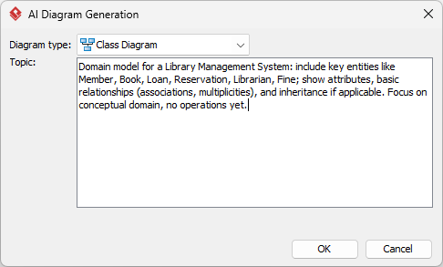
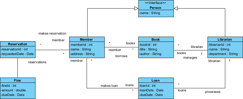
- The AI generates a class diagram based on your description. Review the classes, attributes, and relationships.
- Refine manually: rename classes/attributes for clarity, adjust multiplicities, add missing associations, or delete irrelevant elements. We’ll cover detailed editing next.
Drawing a Class Diagram Manually (Domain Model)
For full control or when refining the AI draft, create the class diagram manually. We’ll build the same Library Management domain model.
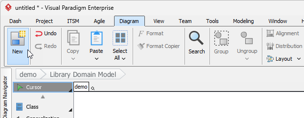
- Select Diagram > New from the main menu.
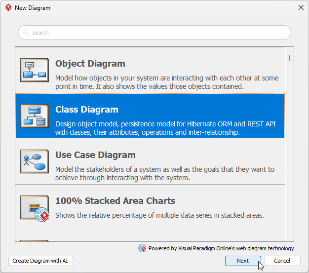
- Choose Class Diagram and click Next.
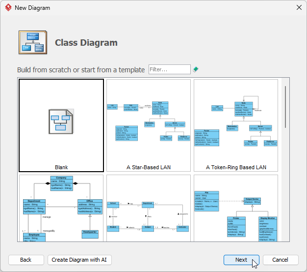
- Select Blank and click Next.
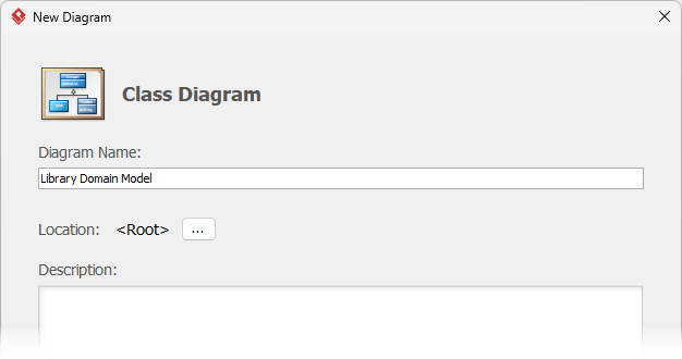
- Name the diagram (e.g., “Library Domain Model”) and click OK.
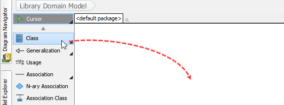
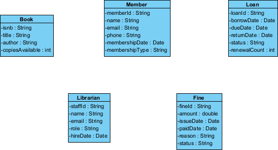
- Create the first class: From the toolbar (left), click Class, then click on the canvas. Name it Book. Double-click to open specification and add attributes (e.g., ISBN: String, title: String, author: String, copiesAvailable: int).
- Add more classes using the same method: Member, Loan, Librarian, Fine.
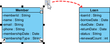
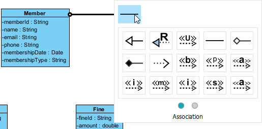
- Create associations: Hover over Member, drag Resource Catalog icon → Loan class.
- Select Association.
- Set multiplicity (Member 1 → Loan 0..*).
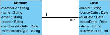
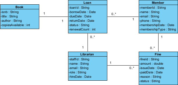
- Continue building relationships: Loan references Book (1 Loan → 1 Book), Member pays Fine (optional extend-like), Librarian manages Loan.
- Finalize and layout: Use auto-layout or drag to arrange. Your diagram should look like this (conceptual domain model):
Drawing a Component Diagram Manually
Now model the modular implementation. We’ll keep it simple: major subsystems realizing the domain/use cases. Create manually for control.
- Create new diagram: Diagram > New.
- Choose Component Diagram and click Next.
- Select Blank and click Next.
- Name the diagram (e.g., “Library Components”) and click OK.
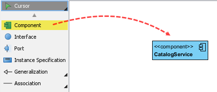
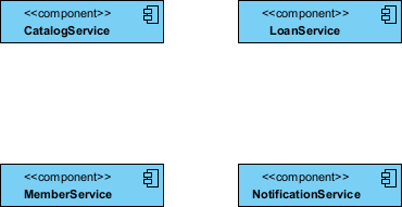
- From toolbar, click Component, draw on canvas, name it CatalogService (provides book search/browse).
- Add more components: LoanService, MemberService, NotificationService.
- Add interfaces: Hover over CatalogService, drag Resource Catalog to the left.
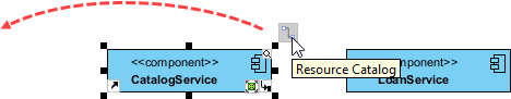
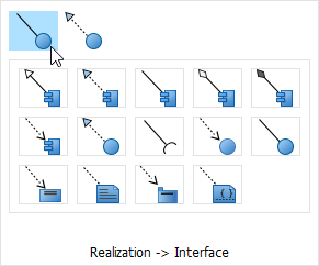
- Select Realization -> Interface.
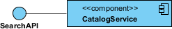
- Name the interface SearchAPI.
- Connect the interface from LoanService. First, move LoanService to the left of SearchAPI.
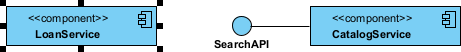
- Press on Resource Catalog and drag to the Interface ball.
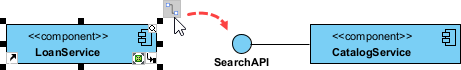
- Select Usage.
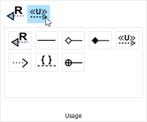
- Release the mouse button. A ball-and-socket joint is formed.

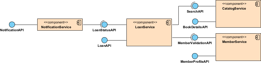
- Complete simple wiring: LoanService provides LoanStatusAPI (used by NotificationService for due reminders).
Creating a Deployment Diagram (Reusing Components)
Finally, show runtime deployment. Reuse the components from above as artifacts deployed on nodes.
- Create new diagram: Diagram > New.
- Choose Deployment Diagram and click Next.
- Select Blank and click Next.
- Name the diagram (e.g., “Library Deployment”) and click OK.
- Add nodes: Toolbar → Node → draw Web Server, Application Server, Database Server.
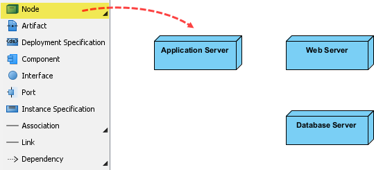
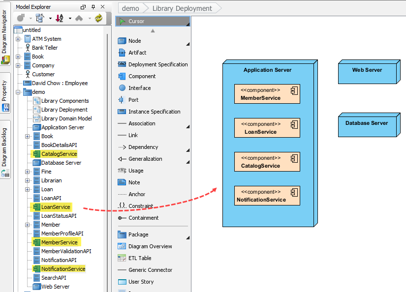
- Reuse components: From Model Explorer (left pane), drag CatalogService, LoanService, etc., onto appropriate nodes (e.g., LoanService and MemberService on Application Server).
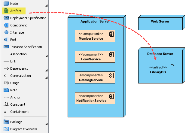
- Add artifacts if needed (e.g., <> LibraryDB on Database Server).
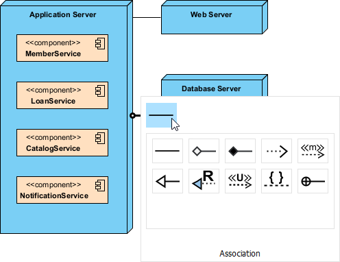
- Show communication: Connect nodes with Association or Communication Path (e.g., Web Server → Application Server → Database Server).
Here is the final Deployment Diagram: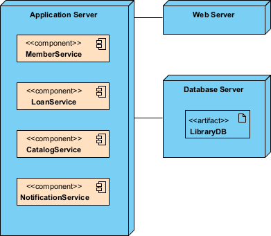
Well done! You’ve now modeled structure from domain (classes) to modules (components) to runtime (deployment) — all driven by the use cases from Module 2.