


Introduction
In the world of software development, creating a robust and efficient application involves careful planning and design. Two fundamental tools at the heart of this process are Class Diagrams and Entity-Relationship Diagrams (ERDs). Class Diagrams allow us to visualize the structure and behavior of our software, while ERDs help us model the underlying data and database schema. However, the key to successful software development lies in finding the right balance between these two essential aspects.
Class Diagrams vs ERD
Class diagrams and Entity-Relationship Diagrams (ERDs) are two different types of diagrams used in software development to represent different aspects of a system, but they are related in the sense that they both help in modeling and designing software systems.
- Purpose and Focus:
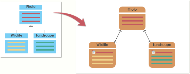
- Class Diagram: Class diagrams are primarily used in object-oriented modeling and design to represent the static structure of a system. They focus on the classes or objects in a system, their attributes, methods, relationships, and the inheritance hierarchy.
- ERD (Entity-Relationship Diagram): ERDs are used to model the data or database schema of a system. They focus on entities (tables), their attributes (columns), and the relationships between these entities. ERDs are typically associated with database design.
- Elements:
- Class Diagram: In a class diagram, you will find classes, attributes, methods, associations, generalization/specialization relationships (inheritance), and dependencies.
- ERD: In an ERD, you will find entities (tables), attributes (columns), relationships (one-to-one, one-to-many, many-to-many), and keys (primary keys, foreign keys).
- Relationship Between Class Diagrams and ERDs:
- In software development, there’s often a strong connection between the application’s data model (ERD) and its object-oriented design (class diagram).
- Mapping Entities to Classes: In many cases, each entity in an ERD can be mapped to a class in a class diagram. For example, if you have an “Employee” entity in your ERD, you may create an “Employee” class in your class diagram.
- Mapping Attributes: Entity attributes (columns) can be mapped to class attributes or properties. For instance, a “Name” attribute in the ERD might correspond to a “name” property in the class.
- Mapping Relationships: Relationships between entities in an ERD can be represented as associations between classes in a class diagram. For example, a one-to-many relationship between an “Order” entity and a “Customer” entity in the ERD can be represented as an association between an “Order” class and a “Customer” class in the class diagram.
- Mapping Keys: Primary keys in an ERD can sometimes be represented as unique identifiers or keys in class diagrams.
- Different Levels of Abstraction:
- Class diagrams are often used during the software design phase to describe the high-level structure of the application in terms of classes, objects, and their interactions.
- ERDs, on the other hand, are more focused on the data storage and retrieval aspects, describing how the data is structured in the database.
In summary, class diagrams and ERDs serve different purposes in software development. However, there is a relationship between them, as the data model represented in the ERD often influences the design of classes and objects in the class diagram, ensuring that the software system’s data and functionality are well-aligned.
Summarizing ERD and Class Diagram
Here’s a table that contrasts Class Diagrams and Entity-Relationship Diagrams (ERDs) in software development:
| Aspect | Class Diagram | Entity-Relationship Diagram (ERD) |
|---|---|---|
| Purpose | Represents the static structure and behavior of classes and objects in the software system. | Models the data structure and relationships in a database system. |
| Focus | Classes, objects, methods, attributes, inheritance, and dependencies. | Entities, attributes (columns), relationships (one-to-one, one-to-many, many-to-many), keys (primary, foreign). |
| Elements | Classes, associations, attributes, methods, generalization/specialization relationships, dependencies. | Entities (tables), attributes (columns), relationships (associations), keys (primary, foreign). |
| Usage Phase | Used during software design and modeling phases. | Used during database design and modeling phases. |
| Representation | Depicts the structure and behavior of classes and their interactions. | Depicts the data storage schema, relationships, and constraints in a database. |
| Mapping | Maps classes to entities, class attributes to entity attributes, associations to relationships, and dependencies to database constraints. | Maps entities to classes, entity attributes to class attributes, relationships to associations, and keys to unique identifiers or properties. |
| Abstraction Level | Represents the high-level view of software components and their interactions. | Focuses on the low-level data storage and retrieval aspects of the system. |
| Example Use Cases | Designing and modeling object-oriented software systems, like applications and systems. | Designing and modeling relational databases for storing and managing data. |
| Tool Usage | Supported by UML modeling tools (e.g., UMLet, Lucidchart, Enterprise Architect). | Supported by database design tools (e.g., MySQL Workbench, ERwin, dbForge Studio). |
| Relationship | There is a connection between class diagrams and the data model (ERD) as the data model may influence class and attribute design. | ERDs are often used as a basis for creating the database schema for a software system, which may influence class design. |
Remember that while class diagrams and ERDs have different focuses, they are often used together in the software development process to ensure that the data structure and software design are well-aligned, especially in applications that rely heavily on databases for data storage and retrieval.
How and When to use Which?
The decision of whether to use a Class Diagram or an Entity-Relationship Diagram (ERD) depends on the specific phase and requirements of your software development project and what you want to communicate or design. Here are guidelines on when to use each:
Use Class Diagrams when:
- Designing Object-Oriented Systems: Class diagrams are most suitable when you are designing object-oriented software systems, such as applications, where you want to represent the classes, their attributes, methods, and their interactions.
- Modeling Software Architecture: Class diagrams are helpful in modeling the static structure of your software, including the relationships between classes and their organization within the system.
- Visualizing Code Structure: They are useful for providing a visual representation of your codebase’s structure, which can be helpful for developers to understand and maintain the code.
- Defining Software Components: Use class diagrams to define and document the key components of your software, their responsibilities, and their relationships.
- Capturing Business Logic: If your focus is on capturing the business logic and functionality of the software, class diagrams are a good choice.
Use Entity-Relationship Diagrams (ERDs) when:
- Designing Databases: ERDs are specifically designed for modeling the data structure and relationships within a database. Use ERDs when your primary concern is data storage, retrieval, and database design.
- Database Schema Design: When you need to create or modify the database schema for your application, ERDs are essential for representing tables, columns, keys, and relationships.
- Data Modeling: ERDs are used for data modeling, making them suitable for industries and applications where data is a primary concern, such as healthcare, finance, and e-commerce.
- Ensuring Data Integrity: They are crucial for ensuring data integrity and enforcing referential integrity constraints in a relational database system.
- Defining Data Entities: ERDs help define and document the entities (tables) in your database, their attributes, and how they are related.
In many software development projects, you’ll find that both Class Diagrams and ERDs are used in tandem. Class diagrams help you design the software’s structure and behavior, while ERDs help you design the underlying data storage. These two diagrams often need to align closely to ensure that the software system functions correctly and efficiently. Therefore, it’s common to transition from class diagrams to ERDs when you are designing the data storage component of your application.
Summary
Effective software design hinges on a harmonious integration of Class Diagrams and ERDs. Class Diagrams guide us in building a well-structured, object-oriented software system by defining classes, their attributes, and interactions. On the other hand, ERDs enable us to create efficient and organized database structures, ensuring that data is stored, retrieved, and maintained seamlessly.
In this document, we explored when to use each diagram, understanding that Class Diagrams excel in representing the software’s high-level architecture and functionality, while ERDs shine in modeling data storage and retrieval. We emphasized that the synergy between these two tools is often the key to developing robust applications. Striking the right balance ensures that our software is not only functionally sound but also capable of handling data efficiently, ultimately leading to software solutions that meet both user needs and technical requirements.
So, whether you’re embarking on a new software project or refining an existing one, remember that the effective use of Class Diagrams and ERDs can make all the difference in delivering a successful and well-rounded software solution.