


Introduction
Robustness Analysis, initially introduced by Ivar Jacobson’s Objectory Method but later excluded from the Unified Modeling Language (UML), is a valuable practice in software engineering. This method involves dissecting the narrative text of use cases to identify the primary set of objects participating in those use cases and categorizing these objects based on their roles. By doing so, robustness analysis facilitates a seamless connection between Use Cases and Domain Classes, effectively aligning with the Model-View-Control (MVC) software architecture.
It’s important to note that robustness analysis is not an integral component of UML but requires the use of stereotypes to be effectively applied. Let’s delve into the key symbols used in Robustness Analysis Diagrams:
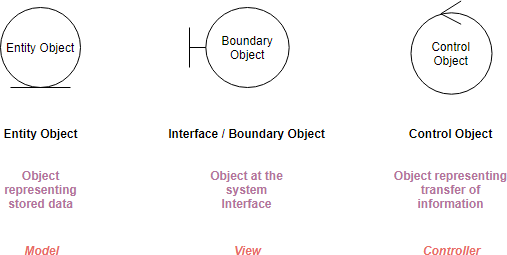
1. Boundary Object (or Interface Object): These are the communication channels through which actors interact with the system.
2. Entity Object: Typically representing objects within the domain model, these entities store and manage system data.
3. Control Objects: Serving as the “glue” between boundary objects and entity objects, control objects play a vital role in coordinating system functions. In the context of MVC, they are akin to controllers.
Robustness Analysis Diagram Overview
To illustrate the concept further, let’s consider a simple use case description in textual format:
“From the student detail page, the teacher clicks on the ‘Add courses’ button, and the system displays the list of courses. The teacher selects the name of a course and presses the ‘Register’ button. The system registers the student for the course.”
This narrative can be translated into a clear Robustness Analysis Diagram:
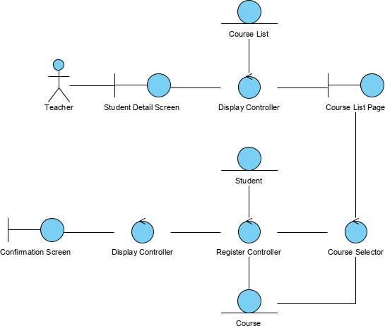
Additionally, you can use a text label to attach the use case description on the right-hand side of the Robustness diagram, enhancing clarity and context.
Four Connection Rules for Robustness Analysis Diagrams
To ensure consistency and adherence to best practices, it’s essential to remember the following four fundamental connection rules for Robustness Analysis Diagrams:
- Actors can only interact with boundary objects.
- Boundary objects can only communicate with controllers and actors.
- Entity objects can only interact with controllers.
- Controllers can communicate with boundary objects, entity objects, and other controllers but not directly with actors.
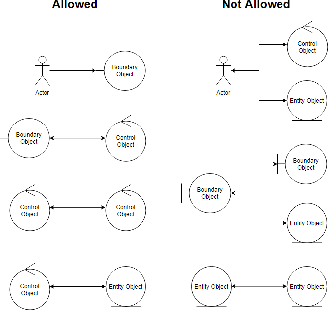
These rules ensure a structured and efficient system design, aligning with the principles of the Model-View-Controller pattern.
The Law of Demeter
Robustness Analysis aligns with the “Law of Demeter” (LoD), emphasizing loose coupling and minimizing knowledge transfer between software units. The LoD encourages the following principles:
- Each unit should have limited knowledge about other units, primarily those closely related.
- Units should communicate only with their immediate “friends” (direct collaborators) and avoid interactions with unrelated or distant units.
- Objects should assume as little as possible about the structure or properties of other objects, promoting information hiding.
These principles facilitate modular and maintainable software design.
Five Steps for Creating Robustness Analysis
- Analyze Use Case Text: Begin by dissecting the use case text one sentence at a time.
- Identify Objects: Draw actors, boundary objects, entity objects, and controllers as per the text’s context.
- Create Connections: Establish connections among the diagram elements.
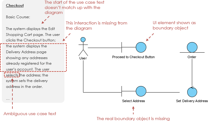
- Maintain Clarity: Ensure that anyone reviewing the diagram can easily match it to the use case text.
- Refine Use Case Text: Modify the use case text as needed to remove ambiguity and explicitly reference boundary objects and entity objects.
Robustness Analysis acts as a bridge, connecting use case descriptions to visual diagrams and fostering a deeper understanding of system functionality.
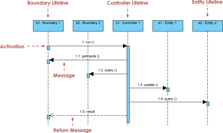
Developing Use Case Scenarios Using MVC Sequence Diagrams
Building on the foundation of Robustness Analysis, you can create use case scenarios, both normal and alternative, using a set of related sequence diagrams following the MVC format. In MVC Sequence diagrams:
- Entities represent system data.
- Boundaries serve as interfaces with system actors.
- Controls mediate interactions between boundaries and entities, orchestrating command execution.
Controllers within the MVC sequence diagrams often correspond to specific use case scenarios and can be visually distinguished using stereotypes on lifelines.
Conclusion
Robustness analysis is a valuable tool in system design, aiding in the efficient translation of use cases into a clear and structured software architecture. When combined with MVC sequence diagrams, it provides a comprehensive approach to software development, promoting modularity and maintainability. By following these practices, you can ensure a smoother software development process and enhance the overall quality of your projects.