


Refining Entity-Relationship Diagrams (ERDs) for Effective Database Design
Problem Description: ER Modeling – A car rental company System
A car rental company needs to create a database to manage their business operations. The company has a large fleet of cars that are rented out to customers for short-term and long-term rentals. The company has several branches in different locations, and each branch has its own fleet of cars.
The company wants to keep track of the cars that are available for rent, the customers who have rented the cars, the rental periods, and the charges for each rental. They also want to keep track of the maintenance schedules for each car and the maintenance activities that have been performed.
The company has the following requirements for their database:
- Cars can be rented out to customers for a specific rental period.
- A customer can rent multiple cars, and a car can be rented by multiple customers.
- The rental charges for each car should be calculated based on the rental period and any additional charges such as insurance or fuel charges.
- The company wants to keep track of the maintenance schedules for each car and the maintenance activities that have been performed.
- The company wants to be able to view reports on the usage of their cars, including the number of rentals, the rental periods, and the revenue generated.
- The company wants to be able to view reports on the maintenance activities performed on their cars, including the type of maintenance performed, the date it was performed, and the cost.
- The company wants to keep track of the customers who rent their cars, including their personal information such as name, address, phone number, and email address.
- The company wants to be able to view reports on their customers, including the number of rentals, the rental periods, and the revenue generated from each customer.
To meet these requirements, an Entity-Relationship (ER) diagram can be created to model the car rental system. The diagram will include entities such as Cars, Customers, Rentals, and Maintenance, and relationships such as Rental, Customer Rental, and Car Maintenance.
Step-by-Step Guide to Developing an ER Diagram for a Database
here’s a step-by-step guide to develop an ER diagram for a database:
- Identify the entities: Start by identifying the different entities that will be included in the database. These entities could be people, places, things, or concepts related to the domain of the database. For example, in a car rental system, the entities could include Cars, Customers, Rentals, and Maintenance.
- Determine the attributes: Next, determine the attributes of each entity. Attributes are characteristics or properties that describe the entity. For example, the attributes of a Car entity could include Make, Model, Year, and License Plate Number.
- Identify the relationships: After identifying the entities and their attributes, determine the relationships between the entities. Relationships are the connections or associations between entities. For example, the relationship between the Car and Rental entities is that a Car can be rented out for a specific rental period.
- Determine the cardinality: The cardinality describes the number of instances of one entity that can be associated with instances of another entity. For example, the cardinality between the Car and Rental entities could be one-to-many, meaning that one car can be rented out to many customers.
- Determine the degree of the relationship: The degree of the relationship refers to the number of entities involved in the relationship. For example, the relationship between the Car and Rental entities is a binary relationship, meaning that it involves only two entities.
- Create a preliminary diagram: Use the information gathered in the previous steps to create a preliminary ER diagram. This diagram should include the entities, attributes, relationships, cardinality, and degree of the relationship.
- Refine the diagram: Refine the ER diagram by reviewing it for accuracy, completeness, and consistency. Make any necessary adjustments or modifications to ensure that the diagram accurately represents the requirements of the database.
- Add constraints: Add any constraints to the diagram that will help ensure data integrity and consistency. Constraints are rules or conditions that restrict the data that can be entered into the database. For example, a constraint could be that a Car entity must have a valid license plate number.
- Finalize the diagram: Once the ER diagram has been refined and constraints have been added, finalize the diagram. The final diagram should accurately represent the database and its requirements.
- Generate the database: Using the finalized ER diagram, generate the database schema. The database schema defines the structure of the database, including the tables, columns, and relationships between them.
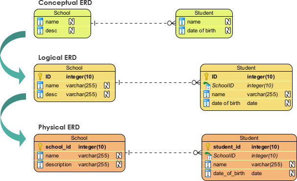
Understanding the Differences between Conceptual, Logical, and Physical Data Modeling
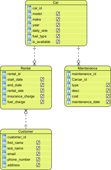
Creating the Conceptual ERD from the Problem Description
The ERD includes four entities: Car, Customer, Rental, and Maintenance. Each entity has its attributes, such as car_id, model, make, year, daily_rate, fuel_type, is_available for Car entity, first_name, last_name, email, phone_number, and address for Customer entity, start_date, end_date, rental_rate, insurance_charge, fuel_charge for Rental entity, and type, description, cost, and maintenance_date for Maintenance entity.
The ERD also shows the relationships between the entities, including the Rental relationship between Car and Rental entities, Customer Rental relationship between Rental and Customer entities, and Car Maintenance relationship between Car and Maintenance entities.
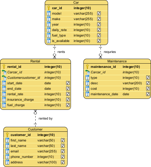
Refine the Conceptual ERD to Logical ERD
The logical ERD includes a more formal, detailed notation emphasizing tables, columns, keys, and relationships. Specifically, the data types of the columns are presented. Besides, labels are added to the relationships (“rents,” “rented by,” and “requires”) to indicate the nature of each relationship.
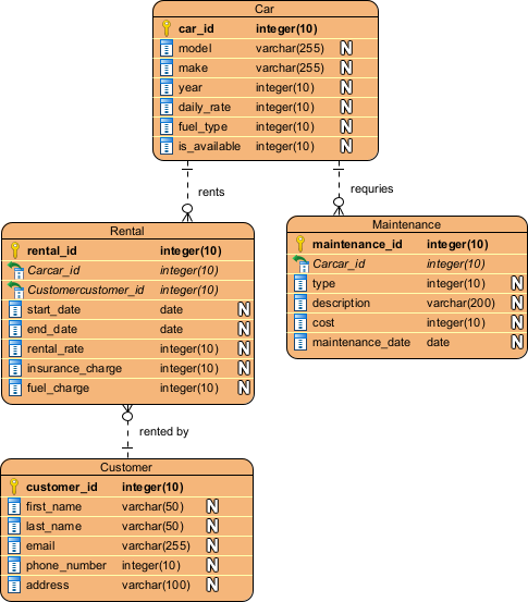
Refine the Logical ERD to Physical ERD
The physical ERD is a ‘database schema diagram’ that provides details enough to implement the database in a specific DBMS. The naming of entities and columns is revised to:
- Support DBMS-specific syntax.
- Ensure the use of the non-reserved words (e.g. order -> purchase_order, desc -> description)
- Fit organizational-specific naming convention
The column ‘desc’ in the entity Maintenance is renamed to ‘description’.
Database Schema Generation: Transforming ERD into a Physical Schema
The database schema is a visual representation of the database structure that defines the organization of data in a relational database management system. The schema is created based on the entity-relationship diagram (ERD) that is used to model the relationships between different entities in a system.
In this case, the ERD was first refined into a logical ERD that defined the relationships between entities such as Cars, Customers, Rentals, and Maintenance, and their respective attributes. The logical ERD helped to establish the relationships and cardinality between the entities.
After refining the logical ERD, the next step was to generate a physical ERD that defines the actual database schema with all the necessary data types, primary and foreign keys, and any constraints. The physical ERD reflects the logical ERD but with more detail on how the data is stored in the database.
Based on the physical ERD, the SQL code was written to create the database schema with the appropriate tables, columns, and relationships between them. Each table in the schema represents an entity in the system, and the columns represent the attributes of that entity. The primary keys were defined to uniquely identify each record in the table, and foreign keys were used to establish relationships between tables.
CREATE TABLE Car (
car_id INT PRIMARY KEY,
model VARCHAR(255),
make VARCHAR(255),
year INT,
daily_rate DECIMAL(10, 2),
fuel_type VARCHAR(255),
is_available BOOLEAN
);CREATE TABLE Customer (
customer_id INT PRIMARY KEY,
first_name VARCHAR(255),
last_name VARCHAR(255),
email VARCHAR(255),
phone_number VARCHAR(255),
address VARCHAR(255)
);CREATE TABLE Rental (
rental_id INT PRIMARY KEY,
start_date DATE,
end_date DATE,
rental_rate DECIMAL(10, 2),
insurance_charge DECIMAL(10, 2),
fuel_charge DECIMAL(10, 2),
car_id INT,
customer_id INT,
FOREIGN KEY (car_id) REFERENCES Car(car_id),
FOREIGN KEY (customer_id) REFERENCES Customer(customer_id)
);CREATE TABLE Maintenance (
maintenance_id INT PRIMARY KEY,
type VARCHAR(255),
description TEXT,
cost DECIMAL(10, 2),
maintenance_date DATE,
car_id INT,
FOREIGN KEY (car_id) REFERENCES Car(car_id)
);
Summary
The article discusses the process of refining entity-relationship diagrams (ERDs) to generate an effective database schema. The ERDs are refined from a conceptual level to a logical level and then to a physical level. The logical ERD establishes the relationships and cardinality between the entities, while the physical ERD defines the actual database schema with all the necessary data types, primary and foreign keys, and constraints.
The SQL code is then written based on the physical ERD to create the database schema with the appropriate tables, columns, and relationships. The article emphasizes the importance of refining ERDs for effective database design and provides insights into the process of generating a database schema from an ERD.