


Exploring the Key Concepts and Elements of Entity-Relationship Diagrams (ERDs)
What is an entity-relationship diagram (ERD)
An entity-relationship diagram (ERD) is a powerful tool for data modeling that allows developers and designers to create a visual representation of data and its relationships. ERDs are based on the concept of entities, which are objects or concepts that have independent existence and can be represented as rectangles in an ERD. Attributes are properties of an entity that describe its characteristics or features, and are represented as ovals in an ERD. Relationships describe how entities are related to each other and are represented as lines that connect the related entities.
- ERDs are commonly used in software development and database design to create a visual representation of data models. They help developers and designers to understand the relationships between entities, and to identify any potential issues with the data model. ERDs also help to ensure that data is organized in a logical and consistent manner, which is essential for efficient and effective database design.
- ERDs are typically created using specialized software tools that allow developers and designers to drag and drop entities, attributes, and relationships onto a canvas. The software then automatically generates the necessary lines and symbols to represent the ERD. ERDs can also be created using pen and paper, although this approach is less common due to the complexity of modern data models.
- ERDs are a valuable tool for database design and management, and are used by a wide range of professionals in the technology industry, including software developers, database administrators, and data analysts. ERDs have evolved over time, with new notations and techniques being developed to improve their effectiveness and efficiency. However, the fundamental concepts of entities, attributes, and relationships have remained consistent, making ERDs an essential tool for anyone involved in database design and management.
The Evolution of Entity-Relationship Diagrams (ERDs) over Time
Entity-relationship diagrams (ERDs) have a rich history, dating back to the 1970s when they were first introduced as a way to model data in database systems. ERDs were initially developed as part of the structured analysis and design techniques that were popular in the 1970s and 1980s.
- The originator of the ERD was Peter Chen, a computer scientist who first introduced the concept in his 1976 paper, “The Entity-Relationship Model – Toward a Unified View of Data”. Chen’s paper proposed a new approach to data modeling that focused on the relationships between entities rather than the individual data elements themselves.
- Chen’s original ERD notation was simple and easy to understand. It used rectangles to represent entities, diamonds to represent relationships, and ovals to represent attributes. Chen’s notation was widely adopted and became the standard notation for ERDs.
- Over time, other researchers and practitioners in the field of database design and management contributed to the development of ERDs. For example, James Martin, another prominent computer scientist, introduced the concept of data flow diagrams, which were used to model the flow of data between entities in a system.
- In the 1980s, a new notation for ERDs was introduced by James Rumbaugh, Ivar Jacobson, and Grady Booch. This notation, known as the Unified Modeling Language (UML), incorporated many of the concepts of ERDs along with other modeling techniques. UML became the dominant notation for software development in the 1990s and early 2000s.
Today, ERDs continue to be an essential tool for data modeling and database design. While the notation has evolved over time, the fundamental concepts of entities, attributes, and relationships remain the same. ERDs are used in a wide range of applications, including business process modeling, software development, and database design.
The Key Elements of ERD
ERDs use a set of key concepts and elements to represent data models. Understanding these key concepts and elements is critical to creating accurate and effective ERDs. In this article, we will explore the key concepts and elements of ERD.
Entities
Entities are objects or concepts that have independent existence and can be represented as rectangles in an ERD. Examples of entities can include customers, orders, products, employees, and suppliers. Each entity is represented by a unique name that identifies it and makes it distinguishable from other entities.
Attributes
Attributes are properties of an entity that describe its characteristics or features. Examples of attributes include customer name, customer ID, product price, product code, etc. Each attribute has a unique name and a data type (e.g., text, number, date, etc.).
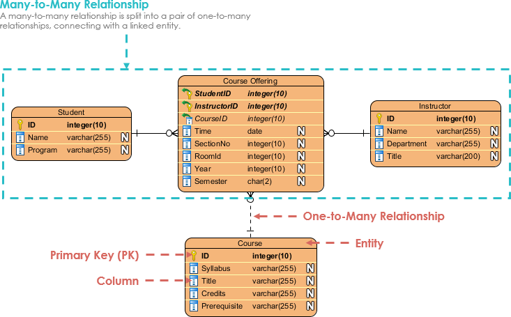
Primary key
A primary key is a unique identifier that is used to distinguish one record in a table from all others. It is a combination of one or more attributes that uniquely identify a record. Primary keys are represented in ERDs as underlined attributes.
Foreign key
A foreign key is an attribute in one table that refers to the primary key of another table. It is used to establish a relationship between two tables. Foreign keys are represented in ERDs as attributes with an arrow pointing to the primary key they reference.
Relationships
Relationships describe how entities are related to each other. Relationships are represented in ERDs as lines that connect the related entities. There are three types of relationships:
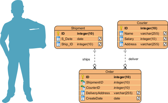
- One-to-one (1:1) relationship: In a one-to-one relationship, each record in one table is related to only one record in the other table. This relationship is represented by a straight line connecting the two entities.
- One-to-many (1:N) relationship: In a one-to-many relationship, each record in one table is related to many records in the other table. This relationship is represented by a line with an arrowhead pointing to the many side.
- Many-to-many (N:N) relationship: In a many-to-many relationship, many records in one table are related to many records in the other table. This relationship is represented by a line with two arrowheads pointing towards each other.
Cardinality
Cardinality describes the number of records that can be related between two tables in a relationship. There are three types of cardinality:
- One (1): Only one record can be related to the other table.
- Many (N): Many records can be related to the other table.
- Zero or one (0..1): Either zero or one record can be related to the other table.
Key Concepts of Data Modeling
ERD, Database Schema, Database, and SQL are all related to each other in the context of database design and management.
- ERD (Entity-Relationship Diagram): ERD is a graphical representation that shows the relationship between entities and their attributes in a database. ERD is used to design and visualize the structure of a database before it is implemented. It is also used to identify the relationships between different entities in a database.
- Database Schema: A database schema is a blueprint or plan for organizing the data in a database. It defines how the data is organized and how the different parts of the database are related to each other. The schema specifies the structure of the tables, the columns in each table, and the relationships between the tables.
- Database: A database is a collection of data that is organized and stored in a way that allows for efficient retrieval and manipulation of the data. Databases are used to store and manage large amounts of data for a wide range of applications, from simple data storage to complex business applications.
- SQL (Structured Query Language): SQL is a programming language used to manage and manipulate relational databases. It is used to create, modify, and query databases. SQL is used to retrieve data from databases, insert new data, update existing data, and delete data. SQL is a standard language used in most relational database management systems (RDBMS) such as Oracle, MySQL, and Microsoft SQL Server.
In other words, ERD and database schema are used to design the structure of the database, while the database is where the data is stored and SQL is used to interact with the database. Together, these components are essential for designing, creating, and managing a database.
Data Modeling Example: CRM System
A company wants to improve its customer relationship management by developing a new system that can manage customer data efficiently. The company has a large customer base, and they want to keep track of customer information such as contact details, purchase history, preferences, and complaints. The current system is inefficient, and it’s difficult to retrieve data quickly. The company wants to develop a new system that can store and manage the customer data more efficiently and provide a better user experience for the employees who will use the system.
To accomplish this goal, the company needs to create a data model that can represent the relationships between different entities such as customers, orders, products, and complaints. The data model needs to be designed in a way that is easy to use, scalable, and can handle large amounts of data. The data model should also be able to generate reports on customer behavior, purchase patterns, and other metrics that can help the company improve its marketing and sales strategies.
The company needs a solution that can handle a large amount of data, manage the relationships between different entities efficiently, and provide quick access to customer information. The data model should also be able to accommodate changes as the company grows and expands its operations. The company is looking for a data modeling solution that can help them achieve their goals and improve their customer relationship management.
Develop an ERD based on the Problem Description
Generate Database Schema Based on the ERD
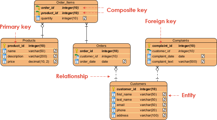
This code creates five tables for the entities we identified, along with their attributes and relationships. The Customers table has a primary key of customer_id, and the Orders and Complaints tables have foreign keys that reference the customer_id in the Customers table. The Orders and Order_Items tables have a composite primary key consisting of both order_id and product_id.
This SQL code can be used to create the database schema for the CRM system described in the problem description.
CREATE TABLE Customers (
customer_id INT PRIMARY KEY,
first_name VARCHAR(50) NOT NULL,
last_name VARCHAR(50) NOT NULL,
email VARCHAR(50) NOT NULL,
phone VARCHAR(20) NOT NULL,
address VARCHAR(100) NOT NULL
);CREATE TABLE Products (
product_id INT PRIMARY KEY,
name VARCHAR(50) NOT NULL,
description VARCHAR(200) NOT NULL,
price DECIMAL(10,2) NOT NULL
);CREATE TABLE Orders (
order_id INT PRIMARY KEY,
customer_id INT NOT NULL,
order_date DATE NOT NULL,
FOREIGN KEY (customer_id) REFERENCES Customers(customer_id)
);CREATE TABLE Order_Items (
order_id INT NOT NULL,
product_id INT NOT NULL,
quantity INT NOT NULL,
PRIMARY KEY (order_id, product_id),
FOREIGN KEY (order_id) REFERENCES Orders(order_id),
FOREIGN KEY (product_id) REFERENCES Products(product_id)
);CREATE TABLE Complaints (
complaint_id INT PRIMARY KEY,
customer_id INT NOT NULL,
complaint_text VARCHAR(500) NOT NULL,
complaint_date DATE NOT NULL,
FOREIGN KEY (customer_id) REFERENCES Customers(customer_id)
);
A Step-by-Step Guide from ERD and Database
Here is a step-by-step guide to creating a database from a problem description:
- Problem Description: Start with a problem description that clearly defines the data to be stored and the relationships between them. This may involve speaking with stakeholders or reviewing existing systems and documentation to identify the entities and their attributes.
- Entity Relationship Diagram (ERD): Create an ERD to visually represent the entities and their relationships. This diagram should include the entities, their attributes, and the relationships between them.
- Database Schema: Based on the ERD, create a database schema that defines the tables, columns, and constraints necessary to store the data. This may involve translating the entities and relationships in the ERD into tables, columns, and relationships in the database schema.
- Data Types and Constraints: For each column in the database schema, select an appropriate data type that can store the necessary data. Add constraints, such as primary keys, foreign keys, and unique constraints, to ensure data integrity.
- SQL Code: Write SQL code that creates the tables, columns, and constraints defined in the database schema. This code can be executed to create the actual database.
- Populate the Database: Once the database has been created, populate it with data using SQL INSERT statements.
- Test the Database: Test the database to ensure that it is functioning correctly and that data is being stored and retrieved accurately.
- Maintain the Database: As the system evolves, continue to maintain the database by making updates and changes to the schema as necessary. This may involve adding new tables or columns, modifying existing tables or columns, or deleting obsolete tables or columns.
Conclusion
ERDs are powerful tools for designing and visualizing data models. Understanding the key concepts and elements of ERDs is critical to creating effective and accurate ERDs. By mastering these concepts, developers can create well-structured, efficient databases that can be easily maintained and scaled over time.
In conclusion, creating a database from an ERD and database schema is a critical step in developing a functional and effective database system. By following a step-by-step approach, starting with a clear problem description and progressing through the creation of an ERD, database schema, and SQL code, it’s possible to ensure that the database meets the needs of the users and is designed with scalability and maintainability in mind. While the process can be time-consuming and complex, taking the time to do it right can save time and effort in the long run and lead to a database system that is both efficient and effective. By following these steps, anyone can create a database that meets their specific needs and contributes to the success of their organization.