


Introduction
Entity-Relationship Diagrams (ERDs) are a fundamental tool in the field of database design and modeling. They provide a visual representation of the data structure within a database, allowing designers, developers, and stakeholders to understand the relationships between different data entities. ERDs serve as a bridge between the conceptual and logical phases of database design, helping to create a blueprint for building efficient and organized databases. In this article, we’ll delve into the key concepts and elements that make up ERDs, offering insights into how they facilitate database design.
- Entities
Entities are the primary building blocks of an ERD. They represent real-world objects, concepts, or things that need to be stored in the database. Each entity is typically associated with a specific table in the database schema. For example, in a university database, entities could include Student, Course, and Professor.
- Attributes
Attributes are characteristics or properties that describe an entity. They define what information is stored within each entity. For instance, a Student entity might have attributes such as StudentID, FirstName, LastName, and DateOfBirth. Attributes can be categorized as simple (atomic) or composite (composed of multiple sub-attributes).
- Relationships
Relationships establish connections between entities in the database. They define how entities are related and interact with each other. There are three main types of relationships in ERDs:
a. One-to-One (1:1): In a one-to-one relationship, each entity instance in one entity is related to exactly one entity instance in another entity. For example, a Passport entity could be related to a Student entity in a 1:1 relationship.
b. One-to-Many (1:N): In a one-to-many relationship, each entity instance in one entity can be related to multiple entity instances in another entity. An example would be a Student entity related to multiple Course entities in a 1:N relationship, as a student can enroll in multiple courses.
c. Many-to-Many (N:M): In a many-to-many relationship, multiple instances in one entity can be related to multiple instances in another entity. To represent N:M relationships in a relational database, an intermediary table, known as a junction table, is often used.
- Cardinality
Cardinality describes the number of occurrences of one entity that can be related to the number of occurrences of another entity in a specific relationship. It is denoted using symbols like “1” for one, “N” for many, and “0” for zero occurrences. Understanding cardinality is crucial for designing efficient databases as it determines the integrity of the relationships.
- Primary Key
A primary key is a unique identifier for each record (row) in an entity. It ensures that each record can be uniquely identified within the table. Primary keys are essential for data integrity and are often implemented as single or composite attributes. In most cases, they are used as foreign keys in related tables to establish relationships.
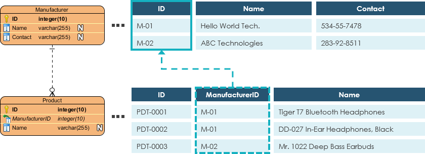
- Foreign Key
A foreign key is an attribute or set of attributes in one table that refers to the primary key of another table. Foreign keys are used to establish relationships between entities and maintain data integrity by ensuring that related data exists in the referenced table. They help maintain referential integrity in the database.
- Weak Entities
Weak entities are entities that do not have a primary key attribute of their own. Instead, they rely on a relationship with a parent (owner) entity to derive their identity. Weak entities are often represented with a double rectangle in an ERD and are dependent on the existence of the parent entity.
Data Modeling: ERD Tips and Tricks
Creating effective Entity-Relationship Diagrams (ERDs) is crucial for designing well-structured databases. Here are some tips and tricks to help you create clear and meaningful ERDs:

1. Start with a Clear Understanding: Before you begin drawing your ERD, make sure you have a thorough understanding of the problem domain, including the entities, their attributes, and the relationships between them. Clear requirements and a solid grasp of the subject matter are essential.
2. Use Standard Notation: Stick to established notation standards like Crow’s Foot or Chen’s notation. Consistency in notation makes it easier for others to understand your ERD and reduces the risk of misinterpretation.
3. Choose Meaningful Entity Names: Give your entities names that accurately represent the real-world objects they model. Use clear and concise naming conventions to make your ERD more understandable.
4. Avoid Overcrowding: Avoid overcrowding your ERD with too many entities and relationships on a single diagram. Break down complex systems into manageable components and create multiple diagrams if needed.
5. Use Proper Cardinality Notation: Clearly indicate the cardinality (1:1, 1:N, N:M) of relationships using proper symbols or text annotations. This helps in understanding how entities relate to each other.
6. Identify Weak Entities: Identify and highlight weak entities in your ERD. Use double rectangles or other visual cues to distinguish them from regular (strong) entities.
7. Define Primary and Foreign Keys: Clearly mark primary keys within each entity and foreign keys in related entities. This shows the unique identifiers and how entities are connected.
8. Maintain Consistency: Ensure consistency in attribute naming and data types across entities. This simplifies the database implementation phase.
9. Use Comments and Annotations: Add comments or annotations to explain complex relationships, constraints, or any other information that might not be evident from the diagram alone.
10. Simplify Relationships: Simplify relationships by using descriptive names and avoiding unnecessary complexity. Try to keep the number of relationships between entities to a minimum while still accurately representing the data model.
11. Validate Against Requirements: Regularly validate your ERD against the project requirements and make sure it accurately reflects the intended functionality of the database.
12. Collaborate and Get Feedback: Collaborate with stakeholders, developers, and other team members to refine your ERD. Feedback from others can help identify issues or improve the design.
13. Keep Versions and Revisions: Keep track of different versions and revisions of your ERD. This helps in documenting the evolution of the database design.
14. Use ERD Software Tools: Consider using ERD modeling software tools like Lucidchart, draw.io, or ERDPlus. These tools often come with features for automating certain aspects of ERD creation and maintaining consistency.
15. Document Assumptions: If you make any assumptions during the design process, document them. Assumptions can help clarify design decisions and serve as a reference for future modifications.
16. Review and Refine: Periodically review and refine your ERD as the project progresses. Changes in requirements or new insights may necessitate adjustments to the data model.
Creating effective ERDs is a skill that improves with practice. By following these tips and tricks, you can create ERDs that not only accurately represent your data model but also make it easier for others to understand and implement the database.
Conclusion
Entity-Relationship Diagrams are indispensable tools in database design and modeling. They provide a structured and visual representation of data entities, attributes, relationships, and their cardinalities. Understanding the key concepts and elements of ERDs is essential for building well-organized and efficient databases that accurately reflect the real-world relationships between data entities. As technology continues to evolve, ERDs remain a vital component of the database development process, aiding in the creation of robust and scalable data solutions.