


What is an Embedded System?
An embedded system is a specialized computer system that is designed to perform dedicated functions or tasks within a larger system or product. Unlike general-purpose computers, which are versatile and can run a wide range of applications, embedded systems are tailored for specific functions and are typically optimized for performance, power efficiency, and reliability within their designated application domain.
Key characteristics of embedded systems include:
- Dedicated Functionality: Embedded systems are purpose-built to perform one or a few specific tasks, such as controlling a microwave oven, managing the engine of a car, processing data from a medical device, or regulating the temperature in a thermostat.
- Integration: These systems are integrated into a larger product or system, where they work as a component or subsystem. They often operate “behind the scenes” and are not directly visible to the end user.
- Hardware and Software: Embedded systems combine both hardware and software components. The hardware includes microcontrollers, microprocessors, sensors, actuators, and other specialized components. The software, often called firmware, is responsible for executing the embedded system’s functions.
- Real-time Operation: Many embedded systems operate in real-time, meaning they must respond to input or events within a specific time frame to ensure proper system functionality. Real-time embedded systems are used in applications like automotive control, industrial automation, and robotics.
- Resource Constraints: Embedded systems often have limited computing resources, including processing power, memory, and storage. These constraints drive the need for efficient programming and optimization.
- Reliability: Embedded systems are designed for high reliability and stability, as they are used in critical applications where failure can have serious consequences, such as in medical devices or aerospace systems.
- Long Lifecycle: Embedded systems are typically expected to have a long lifecycle, and they may need to operate for many years without significant changes or updates.
Examples of embedded systems can be found in various domains, including consumer electronics (smartphones, digital cameras), automotive (engine control units, infotainment systems), industrial automation (PLCs – Programmable Logic Controllers), healthcare (medical devices, patient monitoring systems), and many other fields.
In Short, an embedded system is a specialized computing system designed to perform specific functions within a larger context, emphasizing reliability, real-time operation, and resource optimization.
What is a Deployment Diagram in UML?
A Deployment Diagram in the Unified Modeling Language (UML) is a type of diagram used to depict the physical deployment of software components and hardware nodes in a system. It illustrates how software artifacts (such as executable programs, libraries, and components) are allocated to hardware nodes (such as servers, computers, or devices) in a real-world computing environment.
Here are the key elements and concepts associated with Deployment Diagrams in UML:
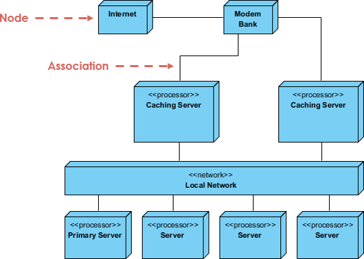
- Nodes: Nodes represent hardware elements or devices in the deployment diagram. These can include servers, workstations, routers, switches, laptops, and more. Each node typically has a name and may include additional details about its properties.
- Artifacts: Artifacts represent software components or modules. These can include executables, libraries, database schemas, configuration files, or any other software-related item. Artifacts are associated with nodes to show where they are deployed.
- Associations: Associations or connectors between nodes and artifacts represent the deployment relationships. These associations indicate that a specific software component is deployed on a particular hardware node. Associations can have labels or stereotypes to describe the type of deployment (e.g., “runs on,” “hosts,” “connects to”).
- Dependency Relationships: In some cases, you may include dependency relationships between artifacts to show how they depend on each other. For example, an application might depend on a database server or a web server.
- Communication Paths: Deployment diagrams can also include communication paths between nodes to show how they interact with each other. This can be important for understanding network communication or data flow in a distributed system.
Deployment diagrams are particularly useful in scenarios where you need to understand and communicate the physical architecture of a system, especially in complex software applications that run on multiple servers or devices. They help stakeholders visualize how software components are distributed across hardware nodes and how these nodes are interconnected.
Deployment diagrams are a valuable tool for system architects, software developers, and system administrators when planning, implementing, and managing the deployment of software systems in a real-world environment.
When to Utilize Deployment Diagrams:
- Integration Requirements: Determine what existing systems the newly introduced system needs to interact with or integrate into. Deployment diagrams help visualize these interactions.
- System Robustness: Assess the robustness requirements, including whether redundancy in hardware is necessary to ensure system availability in case of a failure.
- System Stakeholders: Identify who and what entities will connect to or interact with the system, and define the methods of interaction.
- Middleware and Protocols: Specify the middleware, operating system, and communication protocols the system will utilize for communication and data transfer.
- User Interaction: Clarify which hardware and software components users will directly interact with, such as PCs, network computers, or web browsers.
- System Monitoring: Determine how the system will be monitored once it is deployed to ensure its health and performance.
- Security Measures: Define the level of security required for the system, including the need for firewalls, physically secure hardware, or other security mechanisms.
Purpose of Deployment Diagrams:
- Structural Representation: Deployment diagrams provide a visual representation of the runtime structure of a system, illustrating the hardware elements used and their interconnections.
- Hardware and Communication Modeling: They model physical hardware components and the communication paths that exist between them, aiding in understanding system architecture.
- Planning Tool: Deployment diagrams assist in planning the architecture of a system, helping stakeholders make informed decisions about hardware and software allocation.
- Documentation: They are valuable for documenting the deployment of software components or nodes within a system, aiding in system documentation and communication.
How to Model an Embedded System with UML Deployment Diagram
Creating an embedded system presents challenges that extend beyond mere software development. It involves the intricate management of the physical realm, replete with moving parts susceptible to wear and tear, erratic signal behavior, and nonlinear characteristics. When crafting a model for such a system, one must consider its interaction with the tangible world, requiring contemplation of unconventional devices and nodes.
Deployment diagrams serve as invaluable tools in fostering effective communication between the hardware engineers and software developers engaged in your project. By employing nodes that are imbued with stereotypical resemblances to familiar devices, you can construct diagrams that resonate with both groups. These deployment diagrams also play a pivotal role in deliberating over the interplay between hardware and software. They serve as a means to visualize, articulate, construct, and chronicle the myriad engineering decisions underpinning your system.
To model an embedded system effectively, follow these steps:
- Identify the unique devices and nodes specific to your system.
- Utilize the extensibility features of UML to create system-specific stereotypes with corresponding icons, particularly for uncommon devices. At a minimum, differentiate between processors (housing software components) and devices (which, at this level of abstraction, lack direct software integration).
- Construct a deployment diagram to delineate the relationships among these processors and devices. Likewise, specify the connection between the components in your system’s implementation perspective and the nodes within your system’s deployment perspective.
- As required, elaborate on any intelligent devices by developing a more detailed deployment diagram.
For instance, consider the hardware configuration depicted in the figure below, illustrating a basic autonomous robot. Within this illustration, you will encounter a single node, stereotyped as a processor, denoted as the Pentium motherboard. Encircling this node are eight devices, each labeled as a “device” and depicted with an icon that provides a distinct visual representation mirroring its real-world counterpart.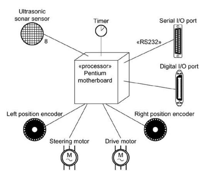
Why embedded systems is most suitably modeled by a UML deployment diagram?
- Physical Mapping: Embedded systems involve the deployment of software components onto specific hardware nodes. A UML deployment diagram is designed to represent the physical mapping of software artifacts onto hardware, making it an ideal choice for modeling the interaction between software and hardware in embedded systems.
- Real-World Context: Embedded systems operate in a real-world context with various hardware devices, sensors, actuators, and communication interfaces. Deployment diagrams allow you to visually capture the relationships between these physical elements and the software components they interact with.
- Clarity of Visualization: UML deployment diagrams use graphical notations that provide a clear and intuitive way to represent hardware nodes, software components, and their connections. This clarity aids in understanding the architecture and deployment of an embedded system.
- Communication: Deployment diagrams facilitate effective communication between different stakeholders involved in the development of embedded systems, including software developers, hardware engineers, system architects, and project managers. They provide a common visual language for discussing deployment-related aspects.
- Resource Allocation: Embedded systems often have resource constraints, such as limited processing power, memory, or energy. Deployment diagrams help in allocating software components to the available hardware nodes while considering these constraints.
- Verification and Validation: Modeling an embedded system’s deployment using UML allows for early verification and validation of the system’s architecture. This can help identify potential issues or bottlenecks before implementation, leading to more reliable and efficient systems.
- Documentation: Deployment diagrams serve as valuable documentation for the system’s physical architecture. They document how software components are distributed across hardware nodes, which can be essential for maintenance, troubleshooting, and system evolution.
- Scalability and Complexity: Embedded systems can range from simple devices to complex, distributed systems. UML deployment diagrams can scale to represent both small-scale and large-scale embedded systems, making them versatile for modeling various levels of complexity.
- Integration with Other UML Diagrams: UML deployment diagrams can be integrated with other UML diagrams, such as class diagrams, sequence diagrams, and component diagrams, to provide a holistic view of the embedded system. This integration helps in capturing both structural and behavioral aspects.
Summary
A UML deployment diagrams are well-suited for modeling embedded systems because they offer a systematic and visual approach to represent the interplay between software and hardware, allowing for effective communication, resource allocation, and documentation in the context of embedded system development.
References
- UML User’s Guide, by Grady Booch,James Rumbaugh,Ivar Jacobson, Addison Wesley, 1999
- What is Deployment Diagram?