


Introduction
Sequence diagrams are a powerful tool in software engineering, specifically in the realm of interaction diagrams. They provide a visual representation of how objects interact over time, allowing developers to understand the flow of messages and communication between different elements in a system. In this comprehensive guide, we will delve into the key components and concepts associated with sequence diagrams.
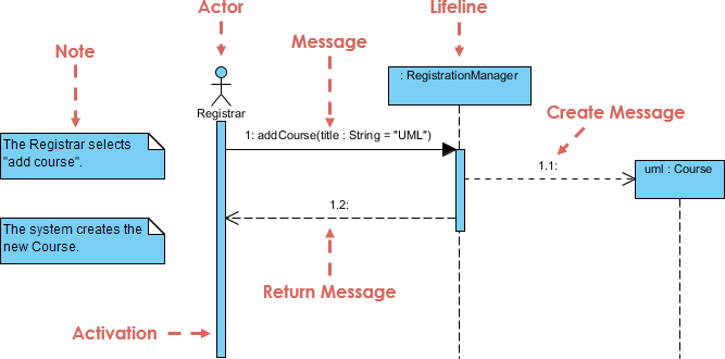
1. Lifelines: Representing Participants
At the core of a sequence diagram are lifelines, which represent individual participants in the system. These participants can be objects, and their interactions are depicted over time. Lifelines are typically shown as rectangles containing the object’s name. If the lifeline represents the classifier owning the sequence diagram, it may be labeled as “self.” Actors from use cases or elements from robustness diagrams can also own lifelines.
2. Messages: The Essence of Communication
Messages are arrows indicating interactions between lifelines. They can be complete, lost, or found, synchronous or asynchronous, and can represent calls or signals. Understanding the nature of messages is crucial for deciphering the communication flow within a system.
3. Execution Occurrence: Activating Control Focus
A thin rectangle running down a lifeline denotes the execution occurrence or activation of a focus of control. This helps in visualizing when an object is actively involved in sending or receiving messages.
4. Self Message: Recursive or Internal Method Calls
A self message is used to represent recursive calls of an operation or when one method within an object calls another method of the same object. It creates a nested focus of control within the lifeline’s execution occurrence.
5. Lost and Found Messages: Navigating Uncharted Territory
Lost messages are those that do not reach their intended recipient, while found messages arrive from unknown senders. These are denoted by special symbols and indicate potential communication issues within the system.
6. Lifeline Start and End: The Birth and Death of Lifelines
Lifelines can be created or destroyed during the timescale represented by a sequence diagram. The start and end of a lifeline are marked by specific symbols, indicating creation or termination.
7. Duration and Time Constraints: Modeling Real-time Systems
To represent the passage of time in real-time systems or time-bound business processes, duration constraints can be applied to messages. This results in sloping lines to indicate the time taken for actions.
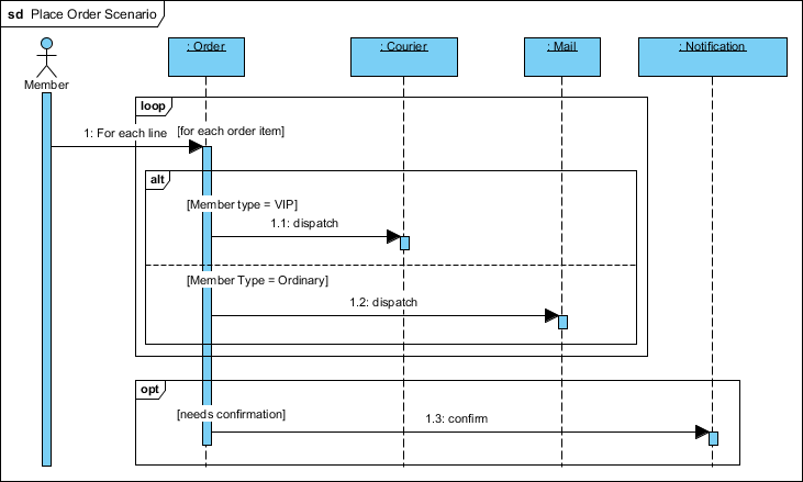
8. Combined Fragments: Adding Procedural Logic
While sequence diagrams are not intended for complex procedural logic, combined fragments offer a mechanism for introducing a degree of logic. These include alternative, option, break, parallel, weak sequencing, strict sequencing, negative, critical, ignore, consider, assertion, and loop fragments.
9. Interaction Occurrence: Referencing Other Diagrams
Interaction occurrences allow for referencing other diagrams, providing modularity and clarity in complex systems. They are denoted by the “ref” keyword in the top left corner of the frame.
10. Gate: Connecting Messages Inside and Outside Fragments
Gates act as connection points for messages inside and outside fragments. They are represented as small squares on a fragment frame and act as off-page connectors for sequence diagrams.
11. Part Decomposition: Understanding Object Relationships
Objects can have multiple lifelines, allowing for the depiction of both inter- and intra-object messages on the same diagram. This part decomposition feature enhances the clarity of relationships within the system.
12. State Invariant and Continuations: Constraints and Flow Control
State invariants impose constraints on lifelines at runtime, while continuations, within combined fragments, can stretch across multiple lifelines.
Conclusion
Sequence diagrams serve as a valuable tool for visualizing and understanding the dynamic aspects of a system. By mastering the elements and concepts discussed in this guide, developers can effectively communicate and analyze the interactions between objects in a software system, leading to better-designed and more maintainable solutions.
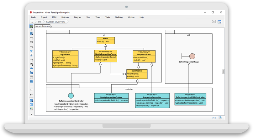
Visual Paradigm Community Edition is an excellent choice for individuals who are embarking on UML modeling for non-commercial purposes. Here are a few reasons why it’s a solid recommendation:
- User-Friendly Interface:
- Visual Paradigm Community Edition offers an intuitive and user-friendly interface, making it suitable for users who are new to UML modeling.
- Free of Charge:
- As a free UML software, it provides a cost-effective solution for individuals and students who are working on non-commercial projects and need UML modeling capabilities without financial constraints.
- Cross-Platform Compatibility:
- The software’s cross-platform support ensures that users can access and utilize it on various operating systems, catering to a diverse user base with different preferences.
- Educational Focus:
- Given its support for students and educational projects, Visual Paradigm Community Edition is designed to meet the needs of learners and those exploring UML concepts in an academic context.
- UML Modeling Capabilities:
- The software provides a comprehensive set of UML modeling tools, allowing users to create a variety of diagrams, including class diagrams, sequence diagrams, and more, which are essential for understanding and communicating software designs.
- Community Support:
- Users can benefit from community support forums and resources, allowing them to seek help, share experiences, and collaborate with others using the same software.
- Stability and Reliability:
- With a history dating back to 2004, Visual Paradigm has established itself as a stable and reliable tool, ensuring a consistent and dependable experience for users.
- Learning Resources:
- Visual Paradigm provides learning resources such as documentation, tutorials, and guides, supporting users in acquiring the necessary skills for effective UML modeling.
For those starting with UML modeling or working on personal projects and educational endeavors, Visual Paradigm Community Edition offers a well-rounded solution that balances functionality, accessibility, and cost-effectiveness.