


Introduction
Use cases play a pivotal role in understanding the functional requirements of a system, acting as a bridge between end-users and developers. Elaborating on use cases is crucial for ensuring a comprehensive understanding of system behavior. One effective way to achieve this is through activity diagrams, which visually represent the flow of activities within a use case.
Elaborating a Use Case
Use cases play a pivotal role in understanding the functional requirements of a system, acting as a bridge between end-users and developers. Elaborating on use cases is crucial for ensuring a comprehensive understanding of system behavior. One effective way to achieve this is through activity diagrams, which visually represent the flow of activities within a use case. In this step-by-step guide, we’ll explore how activity diagrams can be employed to elaborate on a use case.
Let’s dive into the differences between sequence diagrams and activity diagrams in the context of elaborating a use case scenario.
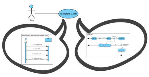
Sequence Diagram: Think of a sequence diagram as a dynamic view of a system, showcasing how different components interact over time to achieve a specific functionality. In the context of a use case scenario, a sequence diagram captures the chronological order of interactions between various objects or entities involved in the use case.
For example, if your use case scenario involves a customer making a purchase online, a sequence diagram would illustrate how the customer interacts with the website, how the website communicates with the server, and how the server responds. It provides a detailed, step-by-step representation of the interactions, showing the order and dependencies of messages exchanged between objects.
Activity Diagram: On the other hand, an activity diagram provides a broader, more holistic view of a use case scenario. It focuses on the flow of activities within the system, highlighting actions, decision points, and parallel activities. In the context of elaborating a use case, an activity diagram would illustrate the overall workflow, depicting different actions and decisions that take place.
Continuing with the online purchase example, an activity diagram might show activities like “Select Item,” “Add to Cart,” “Provide Shipping Information,” and “Payment.” It provides a higher-level understanding of how these activities are structured and how they relate to each other. Activity diagrams are excellent for capturing the procedural aspects of a use case, making them ideal for representing complex business processes.
In summary, while a sequence diagram delves into the dynamic, time-ordered interactions between objects, an activity diagram offers a broader perspective on the flow of activities within a use case scenario. Both diagrams complement each other, providing a comprehensive understanding of the system’s behavior and structure.
Elaborating a Use Case with an Activity Diagram in 10 Steps
In this step-by-step guide, we’ll explore how activity diagrams can be employed to elaborate on a use case.
Step 1: Identify the Use Case:
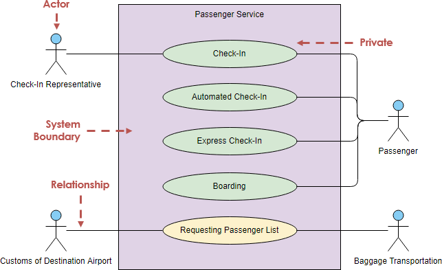
Before diving into the activity diagram, clearly define the scope and objectives of the use case. Understand the primary goals, actors involved, and the expected interactions within the system.
Step 2: Identify Actors and Activities:
Identify the primary and secondary actors associated with the use case. Actors are entities that interact with the system. Enumerate the high-level activities that these actors will perform within the use case.
Step 3: Start with the Initial Node:
In the activity diagram, the initial node represents the starting point of the use case. Connect the initial node to the first activity using a control flow arrow. This signifies the initiation of the use case.
Step 4: Add Actions and Decision Points:
For each identified activity, add action nodes to represent specific tasks or actions that take place. Use decision nodes to depict points where the flow diverges based on certain conditions.
Step 5: Establish Control Flow:
Connect the action nodes and decision nodes using control flow arrows to illustrate the sequence of activities. Ensure that the flow logically represents the order in which actions occur.
Step 6: Include Swimlanes for Actors:
To clearly delineate the involvement of different actors, use swimlanes. Assign each actor to a specific swimlane, making it evident which activities pertain to each actor.
Step 7: Handle Parallel Activities:
In scenarios where multiple activities can occur concurrently, incorporate fork and join nodes. Fork nodes represent the initiation of parallel activities, while join nodes signify the convergence of these parallel paths.
Step 8: Integrate Exception Handling:
Identify potential exceptions or errors that may occur during the execution of activities. Use exception handling nodes to illustrate how the system responds to such deviations and ensure the smooth continuation of the use case.
Step 9: Conclude with an End Node:
Place an end node to signify the completion of the use case. Connect it with the final activities using control flow arrows. This marks the conclusion of the process flow within the use case.
Step 10: Validate and Refine:
Review the activity diagram to ensure it accurately reflects the intended behavior of the use case. Seek feedback from stakeholders and refine the diagram based on their input. Iterate this process until a comprehensive and accurate representation is achieved.
What Next?
Discover the seamless world of UML diagramming with Visual Paradigm Online, your go-to free, online UML tool that effortlessly combines user-friendly design with powerful features. Dive into a realm of convenience with a drag-and-drop-based interface, automatic connector re-routing, and alignment guides for perfect positioning.
The Visual Paradigm Online Free Edition is a treasure trove for students, educators, and non-profit users, offering unlimited diagrams and shapes without expiration, and absolutely ad-free. No training is needed; it’s ridiculously easy to use! But Visual Paradigm Online isn’t just about UML—it’s a versatile diagramming tool. Explore ER diagrams, organization charts, floor plans, business concept maps, and ITIL diagrams with ease.
Elevate your diagramming experience today—unleash your creativity effortlessly and efficiently.
Conclusion:
Elaborating on use cases through activity diagrams provides a visual and intuitive understanding of system behavior. By following these step-by-step guidelines, you can effectively translate use case requirements into a clear and detailed representation, fostering better communication between stakeholders and development teams.