


State diagrams, also known as state machines or finite state machines, are a visual representation of how a system or process behaves over time. They consist of a set of states, transitions between states, and events that trigger those transitions. By breaking down a system’s behavior into discrete states and transitions, a state diagram can help designers and developers better understand how the system works and identify potential issues or areas for improvement.
State diagrams can be used to model a wide variety of systems, from simple machines like vending machines to complex software applications. They can be especially useful for modeling systems with complex or non-linear behavior, where it may be difficult to understand how the system responds to different inputs or conditions. Overall, state diagrams are a powerful tool for system modeling because they provide a clear, intuitive way to visualize a system’s behavior and can help designers and developers identify and address potential issues early in the design process.
Learning State Diagrams with Simple Examples
This article is aimed at readers who want to learn how to create a state diagram for a system, using the example of a vending machine. By presenting both a simple and a more detailed version of the state diagram, the article provides readers with a step-by-step tutorial for how to create a state diagram and how to refine it over time as requirements become clearer. By using the vending machine example, the article makes the concept of state diagrams more concrete and accessible to readers who may not have a technical background in systems modeling or design. Overall, the article is a useful resource for anyone who wants to learn how to create a state diagram for a system and understand its benefits for system modeling.
Example 1: Vending Machine
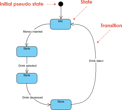
Problem Description: Create a state diagram for a vending machine that dispenses drinks when the correct amount of money is inserted.
Step 1: Identify the States
The first step in creating a state diagram is to identify the states that the system can be in. For a vending machine, some possible states might include:
- Idle: waiting for user input
- Money inserted: user has inserted money but hasn’t made a selection
- Drink selected: user has selected a drink but hasn’t yet received it
- Drink dispensed: user has received the selected drink
Step 2: Identify the Events and Transitions
The next step is to identify the events that can trigger transitions between the states. In this case, the possible events might include:
- Money inserted
- Drink selected
- Drink dispensed
Based on these events, we can identify the following transitions:
- Idle -> Money inserted: when the user inserts money
- Money inserted -> Drink selected: when the user selects a drink
- Drink selected -> Drink dispensed: when the machine dispenses the selected drink
- Drink dispensed -> Idle: when the user takes the drink and the machine is ready for the next transaction
Step 3: Draw the State Diagram
Using the states and transitions we’ve identified, we can draw the state diagram:
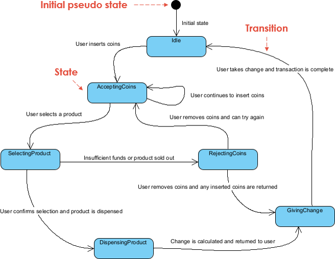
A More Realistic Requirement for the Vending Mach
The simple version of the vending machine problem presented a basic state diagram that showed the different states and transitions involved in the vending machine’s behavior. However, in a real-world scenario, a vending machine would need to have more complex behavior to handle situations like insufficient funds or sold-out products. In the revised version of the problem, we added more detail to the state diagram to reflect these scenarios and provide a more realistic example of how a vending machine could be designed.
Here’s a revised problem description for the detailed version of the vending machine:
A vending machine needs to be designed that allows users to purchase products using coins. The vending machine should have the following behavior:
- Initially, the vending machine is in the
Idlestate, waiting for a user to insert coins. - When a user inserts coins, the vending machine transitions to the
AcceptingCoinsstate and continues to accept coins until the user selects a product or removes their coins. - If the user selects a product, the vending machine transitions to the
SelectingProductstate, where the user can confirm their selection. - If the user confirms their selection, the vending machine transitions to the
DispensingProductstate and dispenses the selected product. - After the product is dispensed, the vending machine calculates any necessary change and transitions to the
GivingChangestate to return the change to the user. - Once the user takes their change, the vending machine transitions back to the
Idlestate and the transaction is complete. - If the user does not have sufficient funds or the selected product is sold out, the vending machine transitions to the
RejectingCoinsstate and returns the inserted coins. From here, the user can either try again or remove their coins and exit the transaction.
This vending machine can be represented using a state diagram with the different states and transitions described above. The diagram can be implemented using a variety of programming languages and frameworks to create a functional vending machine.
Develop A More Detailed State Chart for the Vending Machine
It’s important for readers to understand that problem-solving is often an iterative process, and that requirements for a system may evolve over time. This means that it’s okay to start with a simple version of a problem and gradually revise it as you gain a better understanding of the requirements and constraints involved.
For example, in the case of the vending machine problem, you may start with a basic state diagram that shows the vending machine’s primary states and transitions. As you explore the problem further, you may discover that there are additional scenarios to consider, such as sold-out products or the need to return change to the user. You can then revise the state diagram to reflect these new requirements.
By taking an incremental approach to problem-solving, you can avoid getting overwhelmed by the complexity of the problem and ensure that your solution is well-designed and meets the needs of your stakeholders. This approach also allows you to iterate and refine your solution as you receive feedback and gain a deeper understanding of the problem space.
Summary
The article discusses how to create a state diagram for a system, using the example of a vending machine. The initial state diagram presented is a simple version that shows the primary states and transitions involved in the vending machine’s behavior. The article then presents a more detailed version of the state diagram that takes into account additional scenarios, such as insufficient funds or sold-out products. The article emphasizes the importance of taking an incremental approach to problem-solving, starting with a simple version of the problem and gradually refining it as requirements and constraints become clearer.


