


Introduction
In UML (Unified Modeling Language), interaction diagrams are a category of diagrams used to visualize and describe the dynamic aspects of a system or software application. These diagrams focus on illustrating how different objects or components within the system interact with each other over time. Interaction diagrams are particularly useful for modeling and understanding the flow of messages, actions, and events that occur during the execution of a use case or scenario.
Interaction diagrams are essential tools in UML for capturing and communicating the dynamic behavior of a system. They help software developers, designers, and stakeholders understand how different parts of a system interact and communicate during various scenarios, aiding in the design, analysis, and communication of system behavior.
4 Types of Interaction Diagrams
There are two primary types of interaction diagrams in UML:
- Sequence Diagrams: Sequence diagrams depict interactions between objects or components in a time-ordered sequence. They are often used to model the behavior of a single use case or scenario. In a sequence diagram, you represent objects as lifelines (vertical lines) and show the messages exchanged between these lifelines over time. This diagram helps in visualizing the chronological order of interactions and the messages exchanged between objects.
- Communication Diagrams: Communication diagrams, also known as collaboration diagrams, provide a different perspective on object interactions. They emphasize the structural relationships between objects and how they collaborate to achieve certain behaviors or scenarios. In a communication diagram, you depict objects as nodes, and connecting lines represent the interactions or messages exchanged between them. These diagrams are useful for understanding the relationships between objects in a system.
Two Other Interaction Diagram Variants
Interaction diagrams encompass two other variants, each defined in a distinct subclause. These Interaction Diagram variants include
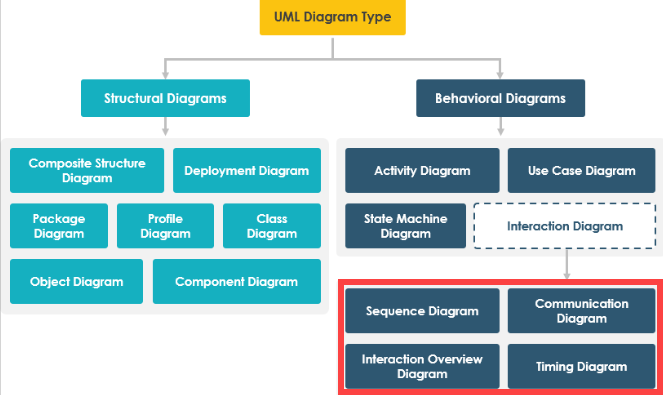
- Interaction Overview Diagrams : Interaction Overview Diagrams define interactions in a manner that emphasizes an overview of the control flow. These diagrams incorporate notational elements similar to those found in Activity diagrams, such as flow lines, forks, joins, and more. However, it is essential to note that while the notation and general purpose of these elements resemble those in Activity diagrams, their detailed semantics differ significantly. Consequently, modelers should avoid interpreting Interaction Overview Diagrams as if they were Activity diagrams.
- Timing Diagrams: Timing Diagrams serve as a means to illustrate interactions when the primary objective is to analyze time-related aspects.
Interaction Diagram: 4 Variants Summary
These interaction diagrams serve different purposes and are used in various scenarios to model the dynamic behavior of systems in UML.
Here’s a table summarizing the four primary types of interaction diagrams in UML:
| Interaction Diagram Type | Purpose and Focus | Key Elements |
|---|---|---|
| Sequence Diagrams | Depict time-ordered interactions between objects or components. | Lifelines (vertical lines representing objects or components), messages, and their ordering. |
| Communication Diagrams | Illustrate structural relationships between objects and their interactions. | Nodes (representing objects or components), connecting lines (for interactions), and object relationships. |
| Interaction Overview Diagrams | Provide an overview of control flow in interactions. | Notational elements (e.g., flow lines, forks, joins), similar to Activity diagrams but with different semantics. |
| Timing Diagrams | Focus on interactions where timing is crucial. | Time intervals, lifelines, events, and messages with a time dimension. |