


Introduction
Unified Modeling Language (UML) provides a powerful set of tools for modeling various aspects of a system or software application. However, deciding which UML diagram to use can be challenging, as different diagrams serve different purposes. In this guide, we will explore three key UML diagram types: State Diagrams, Sequence Diagrams, and Activity Diagrams. We will help you understand when and why to use each type, providing clarity on their specific use cases and advantages.
- State Diagrams focus on modeling the states and state transitions of an object or system.
- Sequence Diagrams focus on modeling the interactions and message flows between objects or components.
- Activity Diagrams focus on modeling the workflow or business processes within a system.
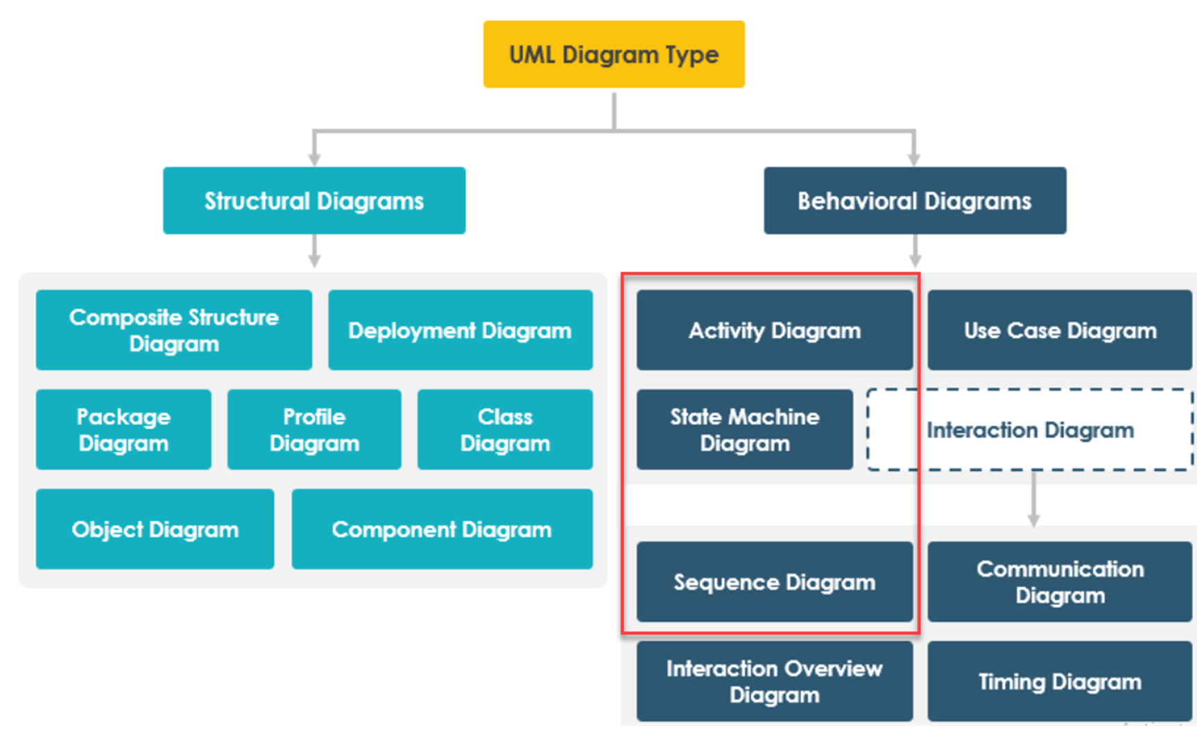
State Diagrams, Sequence Diagrams, and Activity Diagram are categorized as behavior diagrams in UML. Behavior diagrams in UML are used to model and represent the dynamic aspects of a system, illustrating how different components, objects, or processes interact and behave over time. Thank you for pointing out this important categorization.
State Diagram:
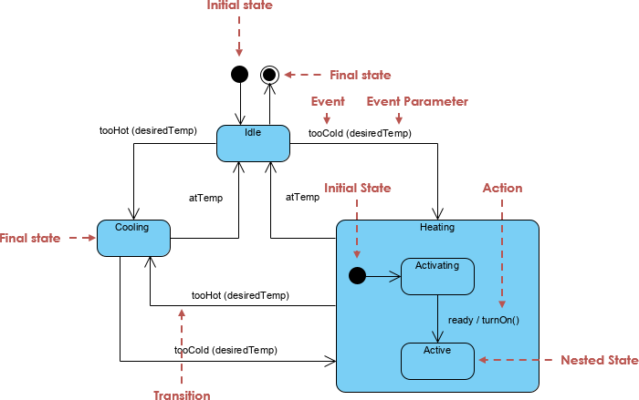
Purpose: State diagrams are used to model the dynamic behavior of an object or a system in terms of its states, state transitions, and events that trigger those transitions.
Elements: States, transitions, events, and actions.
Use Cases: State diagrams are particularly useful for modeling the behavior of objects with complex state machines, such as the behavior of a software component in response to various events.
Sequence Diagram:
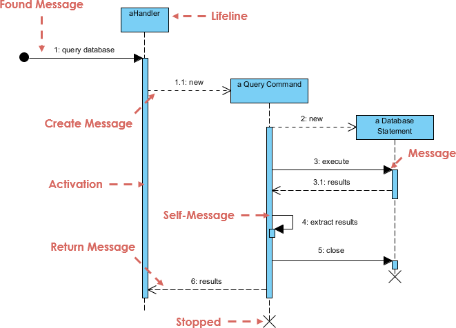
Purpose: Sequence diagrams depict the interactions between different objects or components in a system over time. They show the order of messages exchanged between these objects and the lifelines of the objects involved.
Elements: Lifelines (representing objects or actors), messages, activations, and objects’ state changes.
Use Cases: Sequence diagrams are often used to model the dynamic behavior of a system or to specify the flow of control in a particular scenario or use case.
Activity Diagram:
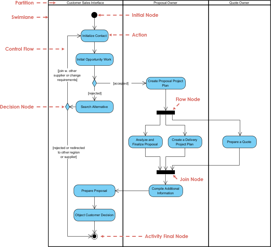
Purpose: Activity diagrams are used to model the workflow or business processes within a system. They represent the flow of activities, decisions, and transitions between them.
Elements: Actions, control flows, decision points, merge points, forks, and joins.
Use Cases: Activity diagrams are commonly used for modeling business processes, workflow systems, or complex algorithms within a software application.
Contrasts the Usage and other key aspects
This table provides a concise overview of the key differences and use cases for State Diagrams, Sequence Diagrams, and Activity Diagrams in UML, helping you understand when to use each type of diagram based on your modeling needs.
The table contrasts the usage, use cases, and other key aspects of State Diagrams, Sequence Diagrams, and Activity Diagrams in UML:
| Aspect | State Diagram | Sequence Diagram | Activity Diagram |
|---|---|---|---|
| Purpose | Model dynamic behavior, states, and transitions of objects or systems. | Model interactions and message flows between objects or components. | Model workflows, processes, and activities within a system. |
| Elements | States, transitions, events, actions. | Lifelines, messages, activations, objects’ state changes. | Actions, control flows, decision points, merge points, forks, joins. |
| Focus | States and state transitions. | Interactions and message sequences. | Workflow, process flow, and activities. |
| Use Cases | – Modeling complex state machines. | – Describing dynamic interactions in a scenario. | – Modeling business processes. – Representing workflow within a system. – Showing algorithmic processes. |
| Typical Symbols | Circles (states), arrows (transitions), rectangles (actions). | Lifelines (vertical bars), arrows (messages), boxes (objects’ lifetimes). | Rounded rectangles (actions), diamonds (decision points), lines (control flows). |
| Time Aspect | Represents the progression of time through state transitions and events. | Represents chronological order of interactions. | Represents flow of control through activities and decisions. |
| Concurrency | Limited representation of concurrency through parallel states. | Can represent concurrent interactions through parallel lifelines. | Easily represents concurrency through parallel activities and forks/joins. |
| Complexity Handling | Suitable for modeling complex state behavior and transitions. | Ideal for capturing complex interactions and message flows. | Well-suited for modeling complex workflows and processes. |
| Interactivity | Focuses on the response to events and state changes. | Depicts interactions between objects with messages. | Illustrates the flow of control and decisions within activities. |
| Notation Clarity | Clear representation of states and state transitions. | Easy to understand message flow and interaction sequencing. | Suitable for visually representing workflows and decision points. |
| Tool Usage | Often used in software design, especially for real-time systems. | Commonly used for system design, software architecture, and scenario analysis. | Widely used in business process modeling and algorithm design. |
| Examples | – Modeling the behavior of a traffic light. – Representing the states of a door (open, closed, locked). | – Describing the flow of user interactions in an online shopping system. – Showing the order of method calls in a software component. | – Modeling the steps in an order processing system. – Representing the workflow of an approval process. |
This table provides a concise overview of the key differences and use cases for State Diagrams, Sequence Diagrams, and Activity Diagrams in UML, helping you understand when to use each type of diagram based on your modeling needs.
When to use which?
Knowing when to use State Diagrams, Sequence Diagrams, or Activity Diagrams in UML depends on the specific modeling needs and the aspects of a system you want to capture. Here are some guidelines on when to use each type of diagram:
- State Diagrams:
- When to Use:
- Use State Diagrams when you need to model and represent the behavior of objects or systems in terms of states and state transitions.
- They are particularly useful for systems with complex state machines where the object’s behavior depends on its current state.
- When you want to illustrate how an object responds to various events and transitions between different states.
- Examples:
- Modeling the behavior of a traffic light (states: red, yellow, green).
- Representing the states of a door (open, closed, locked).
- When to Use:
- Sequence Diagrams:
- When to Use:
- Use Sequence Diagrams when you want to depict interactions and message flows between different objects or components in a system.
- When you need to show the chronological order of method calls, messages, and responses in a specific scenario or use case.
- Ideal for modeling the dynamic behavior of a system from an interaction perspective.
- Examples:
- Describing the flow of user interactions in an online shopping system.
- Showing the order of method calls between different software components.
- When to Use:
- Activity Diagrams:
- When to Use:
- Use Activity Diagrams when you need to model workflows, processes, or activities within a system.
- When you want to represent the flow of control, decision points, and the sequence of actions in a complex process or algorithm.
- Well-suited for business process modeling, workflow modeling, and algorithm design.
- Examples:
- Modeling the steps in an order processing system (e.g., order validation, payment processing).
- Representing the workflow of an approval process (e.g., leave approval).
- When to Use:
Consider the specific modeling goals and the level of detail required when deciding which diagram type to use in your UML modeling endeavors.
Summary
UML diagrams play a crucial role in software design, system analysis, and process modeling. Here’s a brief summary of when to use each of the three main UML diagram types:
- State Diagrams: Choose State Diagrams when you need to model and represent the dynamic behavior of objects or systems in terms of states and state transitions. They excel in scenarios where complex state machines drive an object’s behavior, making them responsive to various events.
- Sequence Diagrams: Opt for Sequence Diagrams when your goal is to depict interactions and message flows between different objects or components in a system. They are perfect for illustrating the chronological order of method calls, messages, and responses in specific scenarios or use cases.
- Activity Diagrams: Utilize Activity Diagrams when you need to model workflows, processes, or activities within a system. These diagrams are well-suited for visualizing the flow of control, decision points, and sequences of actions in complex processes, making them invaluable for business process modeling and algorithm design.
By understanding the distinct purposes and strengths of State Diagrams, Sequence Diagrams, and Activity Diagrams, you can make informed decisions about which UML diagram type best fits your modeling needs, ultimately enhancing the clarity and efficiency of your software development or system design projects.