


Introduction
Unified Modeling Language (UML) provides a powerful framework for visualizing and designing software systems. Among the various types of UML diagrams, class diagrams and object diagrams play essential roles in modeling different aspects of a software system. In this article, we will explore the distinctions between these two diagram types, when to use each, and how they contribute to the overall understanding of a software system’s structure and behavior. Whether you are a software developer, architect, or simply interested in software design, this guide will help you grasp the nuances of class diagrams and object diagrams in UML.
Class vs Object Diagram
- Class Diagram:
- Purpose: Class diagrams are primarily used for modeling the static structure of a software system. They depict the classes, their attributes, methods, and the relationships between classes.
- Elements: Class diagrams typically include classes, interfaces, abstract classes, associations, generalizations (inheritance), dependencies, and multiplicities.
- Use Cases: Class diagrams are useful for designing the overall architecture of a system, defining the classes and their relationships, and illustrating how different classes collaborate to achieve the system’s functionality.
- Example: In a class diagram, you might represent classes like “Car,” “Engine,” and “Wheel,” showing their attributes and methods, as well as relationships like “Car has an Engine” and “Car has Wheels.”
- Object Diagram:
- Purpose: Object diagrams, on the other hand, focus on capturing a snapshot of the runtime instances of classes and the relationships between them at a specific moment in time. They represent a set of objects and their associations.
- Elements: Object diagrams include objects (instances of classes), links (associations between objects), and multiplicity notations to indicate how many instances are involved.
- Use Cases: Object diagrams are particularly useful for testing, debugging, and documenting specific scenarios or instances of a system. They show how objects interact at a given point in time.
- Example: In an object diagram, you might depict instances like “myCar” (an instance of the “Car” class) with its associated instances of “Engine” and “Wheel” at a particular point in the system’s execution.
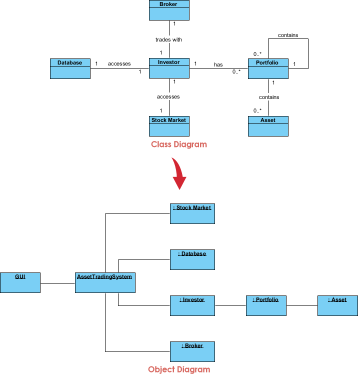
Class diagrams provide a high-level view of a system’s structure, focusing on the relationships and structure of classes, while object diagrams offer a more specific and concrete view by illustrating instances and their relationships at runtime. Both diagrams are essential for understanding and designing software systems, each serving a distinct purpose in the UML modeling process.
When to use which?
Knowing when to use class diagrams and object diagrams in UML depends on your specific modeling needs and the stage of your software development process. Here are guidelines for when to use each type of diagram:
Class Diagrams:
- System Design: Class diagrams are commonly used during the system design phase to define the high-level structure of your software system. Use them when you want to illustrate the classes, their attributes, methods, and their relationships.
- Architecture Planning: Use class diagrams to plan the overall architecture of your software, including the major components and their interactions. This can help in designing a scalable and maintainable system.
- Software Documentation: Class diagrams are great for documenting your software’s static structure. They serve as a reference for developers, making it clear how different classes are related and what attributes and methods they possess.
- Object-Oriented Analysis: In object-oriented analysis, class diagrams are used to represent the concepts and entities in the problem domain, helping in transitioning from requirements to a design.
- Code Generation: Class diagrams can be used as input for code generation tools, where the generated code is based on the class definitions and relationships defined in the diagram.
Object Diagrams:
- Testing and Debugging: Object diagrams are particularly useful during testing and debugging phases. They provide a concrete view of objects and their interactions at a specific moment in time, helping you understand how instances collaborate in runtime scenarios.
- Scenario Illustration: Use object diagrams to illustrate specific scenarios or use cases within your software. This helps in visualizing and communicating how objects interact in different situations.
- Data Visualization: When you need to visualize the actual data in memory or understand how data flows between objects, object diagrams can be valuable.
- Concurrency and Parallelism: In concurrent or parallel systems, object diagrams can help in representing the state of objects and their relationships at different points in time, aiding in identifying synchronization issues.
- Documentation of Instances: Object diagrams can be used to document specific instances of interest, showcasing their attributes and relationships for reference or discussion.
In many cases, you’ll use both class diagrams and object diagrams in conjunction with other UML diagrams like sequence diagrams, use case diagrams, and activity diagrams to provide a comprehensive view of your software system from both a structural and behavioral perspective. The choice of which diagram to use depends on your current modeling goals and the specific information you want to convey.
Contrasting Class diagrams and Object diagrams in UML
Here’s a detailed table contrasting class diagrams and object diagrams in UML:
| Aspect | Class Diagrams | Object Diagrams |
|---|---|---|
| Purpose | Represent the static structure of a system, showing classes, their attributes, methods, and relationships. | Depict a snapshot of specific instances of classes and their relationships at a particular moment in time. |
| Focus | High-level system design, architecture planning, static structure. | Specific runtime scenarios, testing, debugging, and instance visualization. |
| Elements | Classes, interfaces, abstract classes, associations, generalizations, dependencies, multiplicities. | Objects (instances of classes), links (associations between objects), multiplicity notations. |
| Use Cases | – Designing overall system architecture. – Documenting class structure. – Code generation. | – Testing and debugging. – Illustrating specific scenarios. – Data visualization. |
| Time Perspective | Static view of the system structure, doesn’t capture runtime instances. | Snapshot of runtime instances at a specific point in the system’s execution. |
| Scenario Representation | Doesn’t represent specific runtime scenarios; focuses on class relationships. | Represents specific runtime scenarios, showing how objects collaborate at a moment in time. |
| Instance Details | Doesn’t provide details about specific instances; focuses on class-level attributes and methods. | Provides details about specific instances, including their attribute values and relationships. |
| Common Use Cases | – Designing class hierarchies. – Defining class attributes and methods. – Modeling class relationships (association, inheritance, dependency). | – Debugging and troubleshooting specific runtime issues. – Illustrating how instances interact in a specific use case. |
| Lifecycle Phase | System design and development. | Testing and debugging phases. |
| Examples | – “Car” class with attributes like “color” and methods like “startEngine.” – Relationships like “Car has an Engine.” | – “myCar” object instance of the “Car” class with a specific color and state. – Relationships showing how “myCar” collaborates with other objects at a particular moment. |
Summary
Class diagrams serve as a foundational tool for representing the static structure of a software system, illustrating classes, their attributes, methods, and relationships. They find applications in system design, architecture planning, and code generation. On the other hand, object diagrams focus on capturing specific instances of classes and their interactions at runtime, making them invaluable for testing, debugging, and illustrating real-world scenarios. By understanding the purposes and use cases of both class and object diagrams, you can leverage these UML tools effectively to model and communicate various aspects of your software projects.