


Introduction
In the realm of software engineering and system design, effective communication and visualization of a system’s behavior are paramount. This is where Unified Modeling Language (UML) diagrams come into play, offering various tools to represent different facets of a system’s dynamics. Among these, state diagrams and activity diagrams stand out, each serving distinct purposes and providing unique insights into a system’s behavior.
In this article, we delve into the world of state diagrams and activity diagrams, aiming to demystify their characteristics, use cases, advantages, and disadvantages. By understanding the key differences between these two UML diagram types, you will gain valuable insights into when to employ each for optimal results in your software development and system modeling endeavors.
State Diagrams vs Activity Diagrams
State diagrams and activity diagrams are both types of UML (Unified Modeling Language) diagrams used in software engineering and system design to represent different aspects of a system’s behavior, but they serve distinct purposes and focus on different aspects of a system’s behavior. Here’s a comparison of state diagrams and activity diagrams:
- Purpose:
- State Diagram: State diagrams primarily focus on modeling the dynamic behavior of an object or system by representing the various states an object or system can be in and the transitions between those states. They are particularly useful for modeling the behavior of objects with finite states, such as software components or entities with well-defined lifecycle stages.
- Activity Diagram: Activity diagrams, on the other hand, are used to model the flow of activities or actions within a system or a business process. They are typically used to represent the procedural aspects of a system, showing how different tasks or actions are performed and how they are related to each other.
- Elements:
- State Diagram: The main elements of a state diagram include states (representing specific conditions or situations), transitions (depicting how the system moves from one state to another), and events (triggers that cause state transitions).
- Activity Diagram: Activity diagrams consist of activities (representing tasks or actions), control flow arrows (indicating the sequence of activities), decision nodes (for conditional branching), merge nodes (for joining flows), and swimlanes (to partition activities between different actors or subsystems).
- Focus:
- State Diagram: State diagrams emphasize the different states of an object or system and the conditions under which transitions occur between these states. They are particularly useful for modeling real-time systems or systems with complex state-dependent behavior.
- Activity Diagram: Activity diagrams focus on the flow of activities and how different tasks or actions are coordinated within a process or system. They are well-suited for modeling business processes, workflow systems, and software algorithms.
- Usage:
- State Diagram: State diagrams are often used in the design of software systems, embedded systems, and hardware controllers where objects or systems can be in different states and need to respond to events by transitioning between these states.
- Activity Diagram: Activity diagrams are commonly used in business process modeling, software development, and system design to represent the steps and activities involved in a process or workflow.
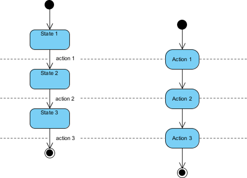
The state diagram, depicted in the left figure below, serves as a visual representation of a state machine that executes actions in response to specific events. It meticulously illustrates the various states within a system and the transitions that transpire between them, driven by the occurrence of events. State diagrams come into their own when modeling reactive systems, those that react to external events, exemplified by applications like traffic lights or vending machines.
Conversely, an activity diagram, showcased in the right figure below, lays out the dynamic flow of activities within a system. It meticulously outlines the sequence of activities that transpire, encompassing decision points, loops, and branching paths. Activity diagrams come to the forefront when modeling systems that engage in a structured sequence of activities, a prime example being the modeling of business processes or the delineation of intricate software algorithms.
State diagrams are used to model the state-dependent behavior of objects or systems, while activity diagrams are used to model the flow of activities or actions within a system or process. The choice between these diagrams depends on the specific aspect of the system’s behavior you want to represent and the level of detail required for your modeling purposes.
Examples for State and Activity Diagrams
Consider a simple object, a traffic light. It has three states: “Red,” “Yellow,” and “Green.” The transitions between these states are triggered by a timer. Here’s how you might represent this behavior using a state diagram:
- States: Red, Yellow, Green
- Transitions:
- Red -> Yellow (Triggered by a timer when the red light’s time is up)
- Yellow -> Green (Triggered by a timer when the yellow light’s time is up)
- Green -> Red (Triggered by a timer when the green light’s time is up)
In this state diagram, you focus on the different states the traffic light can be in and how it transitions between these states based on specific events (timers).
Activity Diagram Example:
Now, let’s consider a business process, such as a purchase order processing system for an online store. Here’s a simplified activity diagram for this process:
- Activities:
- Customer places an order.
- Order is reviewed by the system.
- If the order is valid:
- Inventory is checked.
- Payment is processed.
- Shipping is arranged.
- Order is marked as “Shipped.”
- If the order is not valid:
- Customer is notified.
- Order is canceled.
In this activity diagram, you focus on the sequence of activities involved in the process of handling a purchase order. Each activity represents a specific task, and the arrows show the flow of activities. Decision points (validity check) determine the path the process takes based on conditions.
So, the key differences between the two diagrams in these examples are:
- The state diagram represents different states (Red, Yellow, Green) and how transitions occur between them based on events (timers).
- The activity diagram represents a sequence of activities (order processing) and how they are performed in a specific order, including conditional branching (validity check).
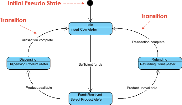
Modeling a Vending Machine Using a State Chart:
In this State Chart representation, the vending machine initiates its operation in the Idle state, providing users with the opportunity to insert coins. Upon inserting an adequate amount of funds, the vending machine advances into the Funds Received state, where users can make their product selection. If the chosen product is in stock, the vending machine shifts into the Dispensing state to deliver the product before returning to the Idle state to conclude the transaction. However, if the selected item is unavailable, the vending machine switches to the Refunding state to reimburse the coins and then reverts to the Idle state, completing the transaction cycle. In cases where users fail to insert sufficient funds, the vending machine promptly transitions to the Refunding state to refund the coins and then returns to the Idle state upon concluding the transaction.
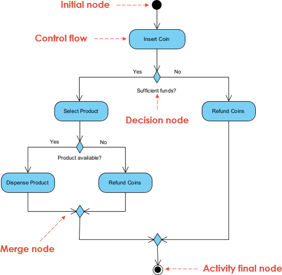
Modeling a Vending Machine Using an Activity Diagram: The provided Activity Diagram offers insight into the sequential events within a vending machine system. Commencing at the start node, users are initially prompted to insert coins. The diagram then features a conditional check to determine if the user has inserted an adequate amount of funds. If sufficient funds are detected, users are granted the ability to select a product.
Subsequently, another conditional check assesses the availability of the selected product. If the product is in stock, the vending machine proceeds to dispense it, with the diagram signifying this by transitioning to the stop node, indicating the successful completion of the transaction. Conversely, if the selected product is unavailable, the vending machine initiates a coin refund process before transitioning to the stop node.
In cases where users do not insert sufficient funds, the vending machine promptly initiates a coin refund process and transitions to the stop node. In either scenario, the transaction concludes, and users can collect any applicable refunds.
These representations, whether through State Charts or Activity Diagrams, provide a clear and structured view of the vending machine’s functionality, helping to analyze its behavior and make improvements if necessary.
Summarizing State Diagrams and Activity diagrams
Here’s a table that contrasts state diagrams and activity diagrams based on various aspects:
| Aspect | State Diagram | Activity Diagram |
|---|---|---|
| Usage |
|
|
| When to Use |
|
|
| Pros |
|
|
| Cons |
|
|
| Examples |
|
|
| Notable Symbols |
|
|
| Key Focus |
|
|
| Level of Abstraction |
|
|
These distinctions should help you choose between state diagrams and activity diagrams based on your specific modeling needs and the nature of the system or process you are representing.
Summary
State diagrams and activity diagrams, though both part of the UML toolbox, cater to different aspects of system modeling. State diagrams excel in capturing the intricate dance of states and transitions within an object or system, making them a go-to choice for systems with well-defined finite states. On the other hand, activity diagrams are masters of illustrating the flow of activities and tasks within a process or system, making them indispensable for modeling business processes, workflow designs, and software algorithms.
State diagrams highlight states and transitions, making them ideal for systems with complex state-dependent behaviors, such as embedded systems and hardware controllers. However, they may become cumbersome for processes with predominantly sequential tasks. In contrast, activity diagrams excel at portraying activity flow and task sequences, making them the preferred tool for documenting procedural logic, especially in business process modeling. Nevertheless, they may not provide as explicit a representation of states and conditions as state diagrams do.
Ultimately, the choice between state diagrams and activity diagrams hinges on your modeling objectives. Whether you’re tracking the life cycle of an object or orchestrating a complex business process, understanding these two UML diagram types will empower you to select the most suitable tool for the job, enhancing the clarity and effectiveness of your system representations.