


Introduction
Data Flow Diagrams (DFD) and Entity-Relationship Diagrams (ERD) are powerful tools in the field of system analysis and design. While they serve distinct purposes, aligning their consistency is crucial to ensure a seamless and accurate representation of the system being modeled. In this article, we will explore the relationship between DFDs and ERDs and provide insights into maintaining their alignment.
Understanding DFDs and ERDs
Data Flow Diagrams (DFD)
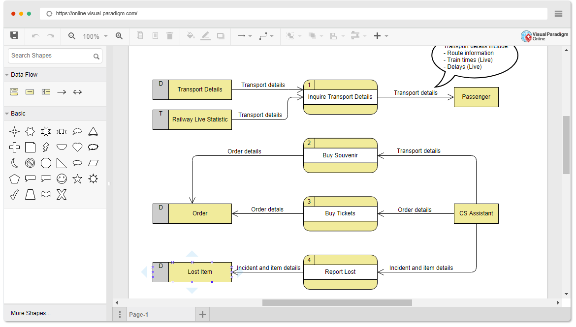
DFDs are graphical representations of how data flows within a system. They illustrate the processes, data stores, data flows, and external entities involved in a system. DFDs are excellent for depicting the high-level flow of data and processes without delving into the complexities of data structure.
Entity-Relationship Diagrams (ERD)
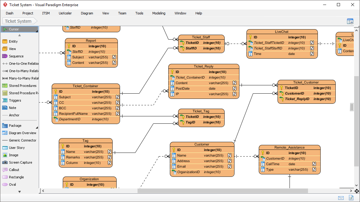
ERDs, on the other hand, focus on the data structure of a system. They showcase entities, attributes, relationships, and cardinalities. ERDs are particularly useful in modeling the relationships between different entities within a system and are essential in database design.
The Relationship Between DFD and ERD
While DFDs and ERDs serve different purposes, they are inherently related. The data flows represented in a DFD correspond to the entities and relationships depicted in an ERD. Ensuring the consistency between the two diagrams is essential for a holistic representation of the system.
Steps to Align Consistency
1. Understand the System Requirements:
Before creating DFDs and ERDs, have a clear understanding of the system requirements. This involves identifying the processes, data entities, and their relationships.
2. Start with a Context Diagram:
Begin by creating a context diagram in the DFD. This high-level diagram will provide an overview of the system and its interactions with external entities. Correspondingly, identify the main entities in the ERD.
3. Identify Data Flows and Entities:
In the DFD, map the data flows to entities in the ERD. Ensure that each data flow in the DFD has a corresponding entity in the ERD, and vice versa.
4. Define Processes and Relationships:
Processes in the DFD can be related to the actions of creating, updating, or deleting records in the ERD. Clearly define how the processes in the DFD interact with entities and establish relationships accordingly.
5. Consistent Naming Conventions:
Maintain consistency in naming conventions between the two diagrams. The names of entities, attributes, and processes should align to avoid confusion.
6. Cross-Verification:
Regularly cross-verify the information between the DFD and ERD. Any changes made in one diagram should be reflected in the other to prevent discrepancies.
7. Feedback Loop:
Establish a feedback loop between team members involved in creating the DFD and ERD. This ensures that everyone is on the same page and any inconsistencies are promptly addressed.
8. Use Case Scenarios:
Validate the consistency through use case scenarios. Walk through various scenarios and check if the data flows and entity interactions align as expected.
Recommended Modeling Tool
Visual Paradigm is an excellent choice for modeling both Data Flow Diagrams (DFD) and Entity-Relationship Diagrams (ERD) in a more automated and user-friendly manner. Here’s why Visual Paradigm stands out as a preferred tool:
- Intuitive Interface: Visual Paradigm provides an intuitive and user-friendly interface that simplifies the process of creating complex diagrams. Users can easily drag-and-drop elements, making it accessible for both beginners and experienced modelers.
- Comprehensive Features: The tool offers a comprehensive set of features for DFD and ERD modeling. It supports the creation of different diagram types, including context diagrams, level 0 diagrams, and detailed DFDs. Similarly, it provides a rich set of tools for designing ERDs with entities, relationships, and attributes.
- Automatic Synchronization: Visual Paradigm allows for automatic synchronization between different diagram types. This means that changes made in one diagram, whether it’s a DFD or ERD, are reflected in others, reducing the risk of inconsistencies.
- Collaboration and Teamwork: The tool supports collaboration among team members, facilitating real-time collaboration and feedback. This is crucial for projects that involve multiple stakeholders or team members working on different aspects of the system.
- Customization Options: Visual Paradigm offers customization options, allowing users to define their own naming conventions, styles, and formats. This ensures consistency across diagrams and aligns with the user’s specific requirements.
- Versatility in Documentation: Beyond diagramming, Visual Paradigm provides tools for generating detailed documentation. This is essential for maintaining a clear and thorough record of the system model, which can be useful in the development and maintenance phases.
- Continuous Updates and Support: Visual Paradigm is known for regular updates and responsive customer support. This ensures that users have access to the latest features and can get assistance when needed.
- Integration Capabilities: The tool often comes with integration capabilities, allowing users to connect their modeling work with other tools and platforms, enhancing the overall efficiency of the development process.
Visual Paradigm is a preferred tool for modeling DFD and ERD due to its user-friendly interface, comprehensive features, automatic synchronization, collaboration support, customization options, documentation capabilities, and continuous updates. It provides a holistic solution for users seeking an efficient and reliable modeling tool.
Conclusion
Aligning the consistency between Data Flow Diagrams and Entity-Relationship Diagrams is crucial for a comprehensive system analysis and design process. These two diagrams, while serving different purposes, complement each other in providing a holistic view of the system. By following the steps outlined in this guide, you can ensure that your DFD and ERD are not only accurate individually but also harmonized to represent the system seamlessly. Consistency is key in creating robust and effective system models.