


In the world of database design, translating abstract concepts into tangible structures is a crucial step toward building functional and efficient database systems. This transformation from Entity-Relationship Diagrams (ERDs) to actual database schemas, including SQL table creation, is a fundamental process in the database development lifecycle. In this article, we will explore how ERDs serve as a bridge between the conceptualization of data and its practical implementation within a database.
Understanding the ERD
Before delving into the intricacies of database implementation, it is essential to comprehend the purpose and components of an ERD. An Entity-Relationship Diagram is a visual representation of the data model, capturing the entities, their attributes, and the relationships between them. The ERD serves as a blueprint for designing the database structure, helping database developers, administrators, and stakeholders to visualize and plan the data organization effectively.
Components of an ERD
- Entities: These are objects or concepts represented within the database, often corresponding to real-world entities like customers, products, or employees. Entities are depicted as rectangles in an ERD.
- Attributes: Attributes define the characteristics or properties of entities. For instance, for a “Customer” entity, attributes might include “CustomerID,” “FirstName,” “LastName,” and “Email.” Attributes are typically shown as ovals in an ERD, connected to their respective entities.
- Relationships: Relationships indicate how entities are connected or associated with one another. They clarify dependencies between entities and can be one-to-one, one-to-many, or many-to-many. Relationship lines between entities specify these associations, and they often come with cardinality indicators that show the allowed quantity of related entities.
Translating ERDs into Database Schemas
The process of moving from ERDs to actual database schemas involves several key steps:
1. Entity to Table Mapping
Entities in the ERD are transformed into database tables. Each attribute within an entity becomes a column in the corresponding table. For instance, if we have a “Customer” entity with attributes “CustomerID,” “FirstName,” “LastName,” and “Email,” we would create a “Customers” table with columns for each of these attributes.
2. Relationship Implementation
Relationships between entities in the ERD are realized through various mechanisms in SQL:
- One-to-One Relationship: In this case, one entity’s primary key becomes a foreign key in the other entity’s table.
- One-to-Many Relationship: The table on the “one” side of the relationship contains a foreign key that references the primary key of the table on the “many” side.
- Many-to-Many Relationship: Typically, this is implemented using a junction table or associative entity that contains foreign keys referencing the tables involved in the relationship.
3. Key Constraints and Data Types
For each column in the database table, data types are specified to define what kind of data can be stored. Additionally, key constraints such as primary keys and foreign keys are defined to enforce data integrity and relationships between tables.
4. Indexing
To improve query performance, indexes are created on columns that are frequently used in search conditions. Indexes provide a quicker way to access data.
5. Data Integrity Rules
Database designers enforce data integrity through constraints. For example, “NOT NULL” constraints ensure that a column cannot contain NULL values, while “UNIQUE” constraints guarantee that values in a column are unique.
SQL Table Creation Example
Let’s illustrate this process with a simple example:
Suppose we have an ERD representing a library system with entities “Book” and “Author” connected by a many-to-many relationship “Author Wrote Book.” Here’s how we would translate this into SQL table creation:
- Create a “Books” table with columns for book attributes (e.g., BookID, Title, PublicationYear).
- Create an “Authors” table with author attributes (e.g., AuthorID, FirstName, LastName).
- Create a “AuthorBook” table to represent the many-to-many relationship. This table would typically include two columns, “AuthorID” and “BookID,” both of which serve as foreign keys referencing the “Authors” and “Books” tables, respectively.
By following these steps, we have successfully translated the ERD into an actual database schema with the necessary tables, relationships, and constraints.
A Case Study on ERD: Online Bookstore
Imagine you are tasked with designing the database for an online bookstore. The system should allow customers to browse books, make purchases, and manage their accounts. Authors and publishers will also have accounts to add and manage books, while administrators will oversee the entire system.
Step 1: Identify Entities
The first step in ERD modeling is identifying the entities relevant to the system. In this case, we can identify the following entities:
- Customer: Represents the individuals who use the online bookstore. Attributes might include CustomerID, FirstName, LastName, Email, and Password.
- Book: Represents the books available for purchase. Attributes might include BookID, Title, Author(s), ISBN, Price, and PublicationYear.
- Author: Represents the authors of the books. Attributes might include AuthorID, FirstName, LastName, and Biography.
- Publisher: Represents the publishers of the books. Attributes might include PublisherID, Name, and Address.
- Order: Represents customer orders. Attributes might include OrderID, OrderDate, TotalAmount, and Status.
- OrderItem: Represents individual items within an order. Attributes might include OrderItemID, BookID, Quantity, and Subtotal.
- Administrator: Represents system administrators. Attributes might include AdminID, FirstName, LastName, Email, and Password.
Step 2: Define Relationships
Next, we determine how these entities are related to each other:
- A Customer can place multiple Orders (one-to-many relationship).
- An Order can contain multiple OrderItems (one-to-many relationship).
- A Book can be written by multiple Authors, and an Author can write multiple Books (many-to-many relationship).
- A Book can have only one Publisher, but a Publisher can publish multiple Books (many-to-one relationship).
- An Administrator oversees the entire system but is not directly related to other entities in this simplified model.
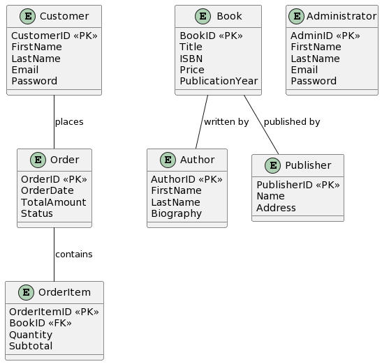
Step 3: Create the ERD
Now, we create the ERD to visually represent these entities and their relationships. Here’s a simplified version of the ERD for our online bookstore:
Step 4: Define Attributes
For each entity in the ERD, we define its attributes. For example:
- Customer: CustomerID (Primary Key), FirstName, LastName, Email, Password.
- Book: BookID (Primary Key), Title, ISBN, Price, PublicationYear.
- Author: AuthorID (Primary Key), FirstName, LastName, Biography.
- Publisher: PublisherID (Primary Key), Name, Address.
- Order: OrderID (Primary Key), OrderDate, TotalAmount, Status.
- OrderItem: OrderItemID (Primary Key), BookID (Foreign Key), Quantity, Subtotal.
Step 5: Normalize the Database (Optional)
Normalization is the process of organizing data in a database to reduce redundancy and improve data integrity. Depending on the complexity of your system, you may need to apply normalization rules to the tables.
Step 6: Implement the Database
Finally, the ERD serves as a guide for creating the actual database tables, defining relationships, constraints, and data types using SQL or a database management tool. This step involves translating the ERD into SQL statements for table creation.
In this case study, we’ve illustrated the process of ERD modeling for an online bookstore. ERDs play a crucial role in designing effective database systems, ensuring that data is organized logically, and relationships are well-defined to support the functionality of the application.
Conclusion
Entity-Relationship Diagrams (ERDs) are invaluable tools for designing and visualizing database structures. They serve as a blueprint for database implementation, guiding the transformation of abstract concepts into concrete database schemas. Through the mapping of entities to tables, the creation of relationships, and the definition of data types and constraints, ERDs bridge the gap between data modeling and real-world database systems. This process, though intricate, is essential for building robust and efficient databases that meet the needs of organizations and applications.