


1. Introduction to ERD
An Entity-Relationship Diagram (ERD) serves as a powerful visual tool for comprehensively mapping the structure of a database. It provides a graphical depiction of how different entities within the database are related to one another, while also highlighting the attributes associated with each entity. ERDs are invaluable during the database design phase as they facilitate the process of defining data requirements and establishing a clear understanding of the database’s architecture. Moreover, they excel at conveying intricate data relationships, making them an indispensable communication aid for both technical and non-technical stakeholders involved in database development projects.
ERD Example
A general Entity-Relationship Diagram (ERD) is a visual representation used in database design to illustrate the structure and relationships within a database.
The way an ERD looks can vary depending on the complexity of the database and the modeling conventions used. However, in a general ERD, you’ll see entities represented as rectangles with their attributes listed inside of it. Lines connecting the entities indicate the relationships between them, and labels on the lines specify the nature of these relationships. Here’s a simple textual representation of what a general ERD might look like:
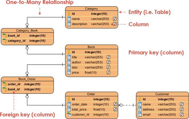
2. Basic ERD Components
Before diving into advanced concepts, let’s briefly review the basic components of an ERD:
- Entity: Represents a real-world object or concept, such as a person, place, or thing. Entities are depicted as rectangles in ERDs.
- Attribute: Describes a property or characteristic of an entity. Attributes are usually displayed as ovals connected to their respective entities.
- Relationship: Illustrates how entities are related to one another. Relationships are depicted as lines connecting entities, often with a verb phrase describing the association.
- Cardinality: Defines the number of instances of one entity that can be related to another entity. Common cardinality notations include “1” for one, “N” for many, and “0..1” for optional relationships.

- Primary Key (PK): A primary key is a unique identifier for each record (row) in a database table. It ensures that each row has a distinct and non-null value, making it a crucial component for data integrity and efficient data retrieval. In an ERD, a primary key is represented by an underlined attribute within an entity.
- Foreign Key (FK): A foreign key is an attribute or set of attributes within one table that refers to the primary key of another table. It establishes a link or relationship between the data in two tables. In an ERD, a foreign key is represented as a solid line connecting two entities, typically with a notation indicating the relationship, such as “1:N” for a one-to-many relationship.
3. Advanced ERD Concepts
a. Subtypes and Supertypes
In some cases, entities can be divided into subtypes, each with its own specific attributes. This concept is used to represent hierarchical relationships within an entity.
Example: Consider a “Person” entity with subtypes “Employee” and “Customer.” The “Employee” subtype may have attributes like “EmployeeID” and “HireDate,” while the “Customer” subtype has attributes like “CustomerID” and “RegistrationDate.”
b. Associative Entities
Associative entities are used to represent many-to-many relationships between two entities. They introduce a new entity to resolve the many-to-many relationship.
Example: In a university database, you might have an “Student” entity and a “Course” entity. To represent the many-to-many relationship between students and courses, you introduce an “Enrollment” entity with attributes like “EnrollmentID” and “EnrollmentDate.”
c. Multivalued Attributes
Multivalued attributes can have multiple values for a single entity. They are often represented as double ovals attached to the entity.
Example: In a “Book” entity, you might have a multivalued attribute “Authors” that can contain multiple author names.
d. Derived Attributes
Derived attributes are attributes whose values can be derived from other attributes within the database. They are typically represented by dashed ovals.
Example: In a “Person” entity, you might have a derived attribute “Age,” which can be calculated based on the “DateOfBirth.”
4. Advanced ERD Examples
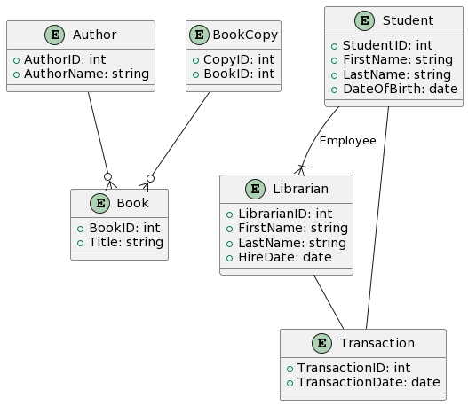
a. Library Management System
Let’s create an ERD for a library management system with advanced concepts:
- Entities: Book, Author, Student, Librarian, Transaction
- Subtypes: Employee (Librarian), Customer (Student)
- Associative Entity: BookCopy (to manage multiple copies of a book)
- Multivalued Attribute: Author’s name
- Derived Attribute: Student’s Age
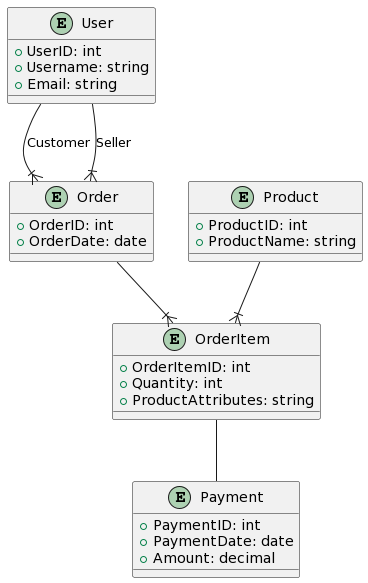
b. E-commerce Platform
Consider an e-commerce platform with advanced features:
- Entities: User, Product, Order, Payment
- Subtypes: Customer, Seller
- Associative Entity: OrderItem (to represent products in an order)
- Multivalued Attribute: Product attributes (e.g., size, color)
- Derived Attribute: Order total price
6. Conclusion
Creating advanced ERDs involves modeling complex data relationships and attributes. Understanding subtypes, supertypes, associative entities, multivalued attributes, and derived attributes is essential for designing comprehensive database systems. With the right tools and concepts, you can effectively represent and communicate the structure of your data models.