


Data Modeling and Object-Oriented Design
Data modeling and object-oriented design are two essential components of software engineering. While data modeling aims to represent data and relationships between entities, object-oriented design focuses on the creation of software objects that encapsulate data and behavior. The relationship between these two concepts is crucial in building robust and maintainable software systems.
In this article, we’ll explore why data modeling is useful for object-oriented design, how entities and entity-relationship diagrams (ERDs) are related to objects in class diagrams, and how data modeling can help to develop your class diagram.
The Complementary Roles of ERDs and Class Diagrams in Software Development
Entity-Relationship Diagrams (ERDs) and class diagrams are both important tools in software development, but they serve different purposes and represent different aspects of the system design.
ERDs are used to represent the data entities and their relationships in a visual way, and they are typically used in the early stages of the software development process to model the data schema. ERDs show the different types of entities and how they are related to each other, and they can also include information about attributes, primary and foreign keys, and cardinality.
On the other hand, class diagrams represent the classes and objects in an object-oriented system, and they are used to model the behavior and structure of the software components. Class diagrams show the relationships between classes, their methods and attributes, and the inheritance hierarchy. They are typically used in the later stages of the software development process, after the data schema has been defined and implemented.
So, why do we need both ERDs and class diagrams in software development? The main reason is that they represent different aspects of the system design, and they are complementary to each other. ERDs help in designing the data schema and defining the relationships between entities, which are important for data storage and retrieval. Class diagrams help in designing the software components and defining their behavior, which are important for implementing the business logic and user interfaces.
By using both ERDs and class diagrams, we can create a more complete and well-structured system design that takes into account both the data and the software components. ERDs provide the foundation for the database schema and data storage, while class diagrams provide the foundation for the software components and their interactions. This can help in creating software systems that are scalable, maintainable, and efficient, as well as easier to understand and modify over time.
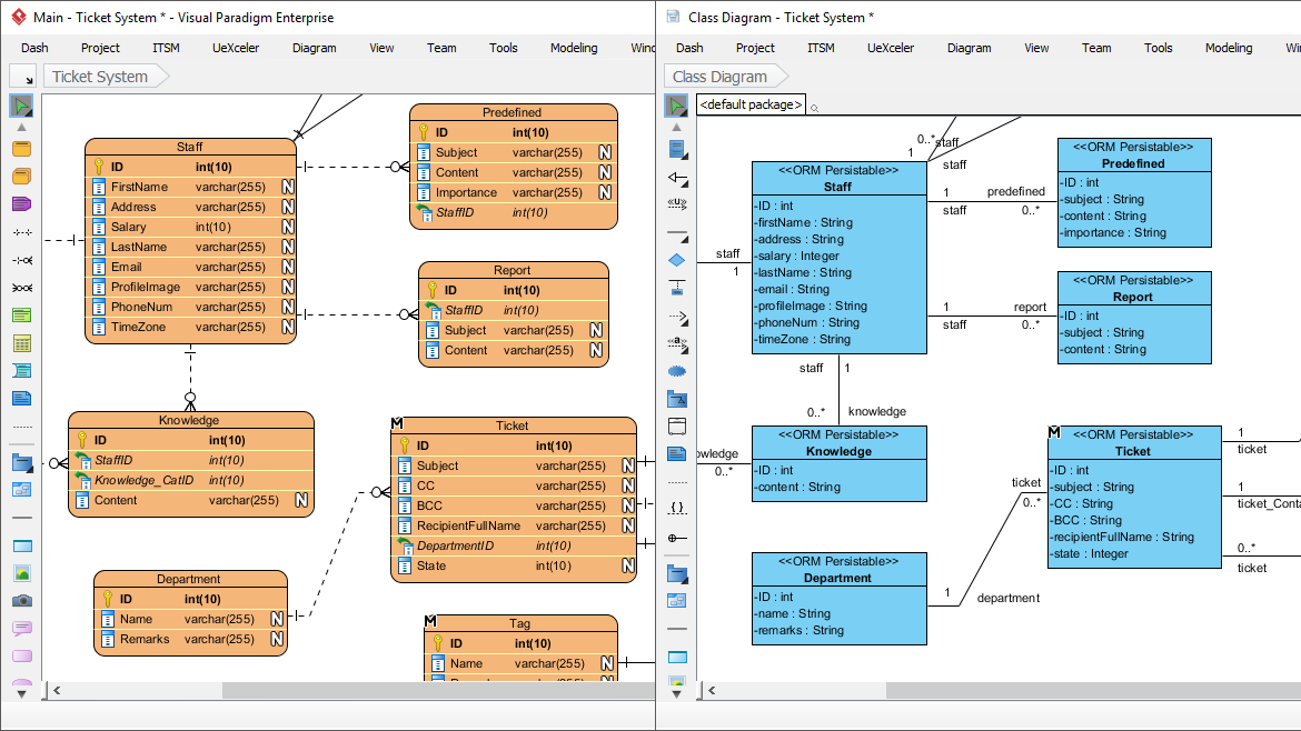
Entity Relationship Diagram vs Class Diagram
ERDs primarily concern the data model layer of a software system, which is often the model layer in the Model-View-Controller (MVC) architecture. The purpose of an ERD is to provide a visual representation of the data schema and its relationships, which can be used as a basis for implementing the data model in a database or other storage system.
On the other hand, class diagrams are more comprehensive in their coverage of the system architecture, as they represent the classes and objects in all three layers of the MVC architecture. In addition to representing the data model layer, class diagrams can also represent the logic and behavior of the system in the controller layer, as well as the user interface and interactions in the view layer. By representing all three layers of the system architecture, class diagrams can help ensure that the system is well-designed and well-integrated, and that the various components work together effectively.
In summary, ERDs are primarily concerned with the data model layer of a software system, while class diagrams cover all three layers of the MVC architecture. Class diagrams provide a more comprehensive view of the system architecture and can help ensure that the system components work together effectively.
Problem Description – Bookstore
We want to develop a system to manage the inventory of a small bookstore. The system should keep track of the books in stock, their authors, and the number of copies available. Customers can buy books, and the system should update the inventory accordingly.
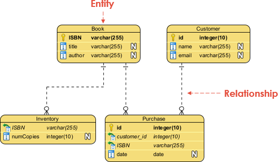
Develop the ERD for the Bookstore System
In this ERD, we have four entities: Book, Inventory, Customer, and Purchase. The Book entity represents the books in the inventory and their authors. The Inventory entity keeps track of the number of copies of each book available. The Customer entity represents the bookstore’s customers, and the Purchase entity keeps track of the books purchased by each customer.
The relationships between the entities are represented by the lines connecting them. We have a one-to-many relationship between Book and Inventory (i.e., a book can have multiple copies in the inventory), a many-to-one relationship between Purchase and Customer (i.e., a customer can make multiple purchases), and a many-to-one relationship between Purchase and Book (i.e., a book can be purchased multiple times).
Develop the ERD
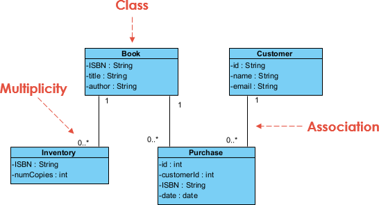
Develop the Class Diagram based on the Logical ERD
In this class diagram, we have four classes: Book, Inventory, Customer, and Purchase. The attributes of each class are represented as private variables. We have the same relationships as in the ERD, but they are represented differently. We have a one-to-many relationship between Book and Inventory, which is represented by a line with an arrowhead pointing from Book to Inventory and the number 1 near the Book class and 0..* near the Inventory class. We have a one-to-many relationship between Customer and Purchase and between Book andPurchase, which are represented by lines with arrowheads pointing from Purchase to Customer and Book, respectively.
By using data modeling and deriving a class diagram, we can create a robust and maintainable software system to manage the inventory of a small bookstore.
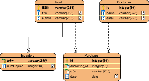
Develop the Physical ERD by Refining the Logical ERD
In this physical ERD, we use the class diagram syntax to represent database tables. We define a Table macro that takes a name and a description as arguments and formats the class accordingly. We also define PrimaryKey and ForeignKey macros to format the primary key and foreign key attributes, respectively.
We create four tables: Book, Inventory, Customer, and Purchase, each with their attributes. We use the [PK] and [FK] annotations to indicate the primary key and foreign key attributes, respectively. We also use the --|> arrowhead to indicate the relationships between the tables.
By using a physical ERD, we can visualize the database schema and its relationships, which can be useful for database design and optimization.
Write SQL to Create the Database Based on the Physical ERD
This schema includes four tables with their attributes and relationships, following the syntax of the SQL language. We use the CREATE TABLE statement to define each table, and specify the attributes along with their data types and constraints, such as PRIMARY KEY and FOREIGN KEY. We also use the REFERENCES keyword to indicate the relationships between the tables.
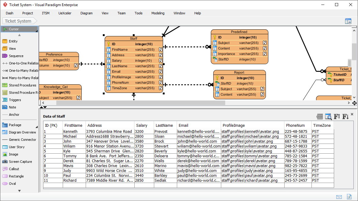
(*Screenshot of Visual Paradigm – Generate Databases from ERD)
This schema can be used to create a physical database instance, where data can be stored and retrieved according to the defined schema.
CREATE TABLE Book (
ISBN VARCHAR(255) PRIMARY KEY,
title VARCHAR(255),
author VARCHAR(255)
);CREATE TABLE Inventory (
ISBN VARCHAR(255) PRIMARY KEY REFERENCES Book(ISBN),
numCopies INT
);CREATE TABLE Customer (
id INT PRIMARY KEY,
name VARCHAR(255),
email VARCHAR(255)
);CREATE TABLE Purchase (
id INT PRIMARY KEY,
customerId INT REFERENCES Customer(id),
ISBN VARCHAR(255) REFERENCES Book(ISBN),
date DATE
);
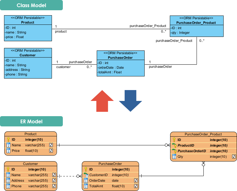
An Alternative Approach to Data Modeling: Object-Relational Mapping
ORM (Object-Relational Mapping) is an alternative means of data modeling that allows developers to interact with a relational database using an object-oriented programming language, without having to write complex SQL queries. In other words, ORM provides a way to map between the relational data model of a database and the object-oriented data model of a programming language.
ORM frameworks like Hibernate, Django ORM, and Sequelize provide a set of tools and APIs that simplify the process of working with databases, by allowing developers to work with objects instead of tables and rows. ORM frameworks provide a way to define object classes that represent database entities, and to map the attributes of those classes to the corresponding database columns. They also provide a way to query the database using object-oriented syntax, which can make code more readable and easier to maintain.
Using ORM can simplify the data modeling process by abstracting away many of the complexities of relational databases, and by providing a more natural way to interact with data in an object-oriented programming language. ORM can also make it easier to switch between different databases or database systems, since the ORM framework handles much of the underlying database-specific details.
However, it is important to note that ORM is not always the best solution for every situation. There can be performance and scalability trade-offs associated with ORM, and it may not be well-suited to certain types of applications or data models. Ultimately, the choice between using ORM or traditional data modeling techniques will depend on the specific requirements of the project, and the expertise and preferences of the development team.
Conclusion
Data modeling is a crucial step in object-oriented design as it allows us to represent the data and relationships between entities in a structured way. By using tools such as Entity-Relationship Diagrams (ERDs) and class diagrams, we can visualize the data schema and its relationships, which can help in designing efficient and maintainable software systems.
In this article, we demonstrated how to create a physical ERD and derive a class diagram from it. We also generated a database schema based on the physical ERD, which can be used to create a physical database instance. By following these steps, we can create a well-structured database schema that represents the data entities and their relationships in a clear and concise manner.
Overall, data modeling is an important aspect of software development, and by using tools like ERDs and class diagrams, we can design better systems that are easier to understand, maintain, and evolve over time.