


UML (Unified Modeling Language) component diagrams are indeed a valuable tool in software engineering for modeling high-level software components and subsystems. They are especially useful in service-oriented architectures and component-based development projects. Here are some key points about UML component diagrams:
- Modeling Components: UML component diagrams allow you to represent the major software components or modules within a system. These components can be classes, libraries, packages, or even larger subsystems, depending on the granularity of the system you are modeling.
- Defining Interfaces: One of the primary purposes of component diagrams is to define the interfaces between these components. These interfaces specify how components interact with each other, including the methods, data, and services they provide and consume. This is crucial for ensuring proper communication and integration among system parts.
- Visual Overview: Component diagrams provide a clear visual overview of a system’s architecture. This visual representation helps stakeholders, including developers, project managers, and business analysts, to quickly grasp the structure and organization of the software.
- Early Project Stage: Component diagrams are typically drawn early in a project’s lifecycle, during the design and planning phases. They serve as an important tool for seeking approval from stakeholders and ensuring that everyone has a common understanding of the system’s architecture before development begins.
- Implementation Roadmap: Component diagrams can also aid in developing an implementation roadmap. By identifying the major components and their dependencies, development teams can better plan how to build and integrate various parts of the system.
- Reuse and Maintainability: In component-based development, these diagrams help identify opportunities for component reuse, which can lead to more efficient and maintainable software systems. Reusing well-defined components can save time and effort in development.
- Deployment Considerations: While component diagrams primarily focus on the software architecture, they can also include elements that indicate the physical deployment of components on hardware or servers, helping in understanding the system’s deployment topology.
- Evolution of the System: As the project progresses, component diagrams may evolve to reflect changes in the system’s architecture. They serve as living documentation that can be updated to reflect the current state of the software.
The Elements of Component Diagram in UML
A UML (Unified Modeling Language) component diagram consists of several elements that are used to model the high-level structure of a system and its components. Here are the key elements typically found in a UML component diagram:
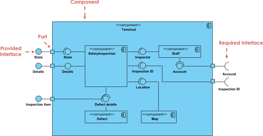
- Component: The primary element of the diagram, representing a high-level, self-contained software module or subsystem. Components can be physical executables, libraries, or logical modules. They are depicted as rectangles with the name of the component inside.
- Interface: Represents the contract or set of operations that a component provides or requires. Interfaces define how components interact with each other. Interfaces are typically shown as small rectangles connected to components with a dashed line.
- Dependency: Indicates a relationship between two components where one depends on the other. Dependencies are shown as dashed arrows pointing from the dependent component to the component it relies on.
- Port: A specific point of interaction on a component where interfaces are connected. Ports are typically small squares or circles attached to a component with lines representing connections to interfaces.
- Provided Interface: Denotes the interface(s) that a component offers or implements. It’s associated with the component using a solid line with an open arrowhead pointing to the provided interface.
- Required Interface: Represents the interface(s) that a component depends on or requires. It’s connected to the component with a solid line and a closed arrowhead pointing to the required interface.
- Assembly Connector: Used to show how components are connected or assembled to form a larger system. Assembly connectors are represented as lines connecting the required and provided interfaces of different components.
- Artifact: Represents a physical piece of the system, such as a file or a binary component. Artifacts can be associated with components to show which components use or contain them.
- Note: Allows you to add explanatory or descriptive information to the diagram. Notes are often represented as small rectangles with a dashed line to the element they are related to.
- Package: Used to group related components together for organizational purposes. Packages are depicted as large rectangles or folders containing components, interfaces, and other elements.
- Constraint: Specifies constraints or conditions that apply to components or interfaces. Constraints can be associated with components or interfaces to provide additional information about their behavior or properties.
These elements collectively help model the structure and relationships of software components and subsystems in a UML component diagram, providing a visual representation of a system’s architecture.
Component Diagram vs Class Diagram
Relating to UML class diagrams, component diagrams offer valuable implementation insights to developers by specifying the interfaces facilitating interactions among various components.
Following implementation, components can be treated as discrete entities for testing in continuous integration deployments.
In contrast to class diagrams, component diagrams abstract away the internal data structures and methods within a component, revealing only the interfaces responsible for external interactions. This decouples the internal workings of a component from the broader system.
Component diagrams foster the creation of modular components, promoting reusability within complex systems and across different projects.
Moreover, they pinpoint opportunities for integrating third-party component packages to enhance system implementation efficiency, thereby reducing project time and costs, especially when in-house expertise is limited.
Summary
UML component diagrams are a crucial part of the software development process, helping to model software components, define their interfaces, and provide a visual representation of the system’s architecture. They play a significant role in early project stages, facilitating communication among stakeholders and guiding the implementation of complex systems.