


Unified Modeling Language (UML) is a powerful tool for visualizing, designing, and documenting software systems. When it comes to modeling complex systems like client/server architectures, UML offers various diagrams to represent different aspects of the system. In this article, we will focus on using UML packages and deployment diagrams to model a client/server system.
Understanding Client/Server Systems
Before we dive into the UML modeling aspect, let’s briefly understand what a client/server system is. In a client/server architecture, a networked system is divided into two main components:
- Client: The client is a user interface or application that requests services or resources from the server. It initiates requests and displays the results to the user. Clients can be desktop applications, web browsers, mobile apps, or any device that communicates with the server.
- Server: The server is responsible for processing client requests and providing the requested services or resources. It listens for incoming requests, processes them, and sends back the responses. Servers can be physical machines, virtual machines, or cloud-based services.
UML Packages for Structuring
In UML, packages are used to group related elements and provide a structured view of a system. To model a client/server system, you can use packages to organize various components and subsystems within the architecture. Here’s a breakdown of how to structure your UML model using packages:
- Client Package: Create a package labeled “Client” to represent the client-side components and functionalities. Inside this package, you can include sub-packages or classes for different client modules, such as user interfaces, user authentication, and communication with the server.
- Server Package: Similarly, create a package labeled “Server” to represent the server-side components. Within this package, you can organize sub-packages or classes for services, databases, and other server-related functionalities.
- Communication Package: To depict the communication between the client and server, create a package called “Communication” or “Networking.” This package will contain elements related to protocols, APIs, and data exchange methods between the client and server.
- Deployment Package: Later, you’ll use a deployment diagram to illustrate the physical deployment of components. Create a package labeled “Deployment” to encapsulate this diagram and any related documentation.
Using Deployment Diagrams
A deployment diagram is a type of UML diagram used to visualize the physical deployment of software components in a system. It represents the hardware and software infrastructure where system components run and communicate. Here’s how to create a deployment diagram for your client/server system:
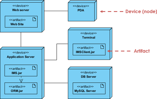
- Nodes: In a deployment diagram, nodes represent physical entities such as servers, workstations, routers, or cloud instances. Identify the nodes that will host your client and server components. Label them appropriately, e.g., “Client Node” and “Server Node.”
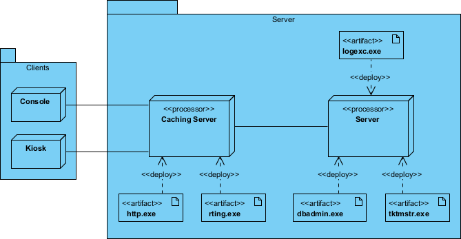
- Components: Represent each software component (client and server) as a separate rectangular box within the respective nodes. Use stereotypes like “<<client>>” and “<<server>>” to differentiate between them. Connect these components to their respective nodes.
- Communication Paths: Use communication paths (lines with arrows) to illustrate the connections and communication flows between client and server components. Include labels to indicate the protocols or methods used for communication.
- Deployment Specifications: You can attach deployment specifications to nodes or components to provide additional details about the hardware, software versions, and configurations used in the deployment.
- Artifacts: If your system involves data storage, you can represent databases or data repositories as artifacts within the server node.
- Deployment Relationships: Use relationships like “uses,” “associates,” or “depends on” to show how components rely on each other or on external resources.
- Constraints: Document any constraints or restrictions related to the deployment, such as security measures or hardware requirements.
Designing a Client/Server System: An Architectural Perspective
When embarking on the development of a software system that extends beyond the confines of a single processor, a cascade of decisions awaits. These decisions range from how to effectively distribute software components across various nodes to establishing communication channels, and devising strategies to handle failures and mitigate noise. At the heart of distributed systems lies the realm of client/server systems, characterized by a clear separation of concerns between the user interface (typically managed by the client) and the data (typically governed by the server).
In either scenario, dividing a system into its constituent client and server parts necessitates making critical decisions regarding the placement of software components and the distribution of responsibilities among them. For instance, a typical management information system adheres to a three-tier architecture, physically distributing the system’s GUI, business logic, and database. Deciding the location of the GUI and database is often straightforward, leaving the challenging task of determining the residence of the business logic.
This is where UML (Unified Modeling Language) deployment diagrams come into play, facilitating the visualization, specification, and documentation of these critical architectural decisions regarding the topology of your client/server system and the distribution of its software components across client and server nodes. Typically, you’ll begin by creating a single deployment diagram for the entire system, complemented by more detailed diagrams that zoom in on specific segments of the system.
Here’s a concise guide to effectively model a client/server system using UML deployment diagrams:
- Node Identification: Commence by identifying the nodes that symbolize the client and server processors within your system.
- Relevant Devices: Highlight devices that hold significance in the system’s behavior. These might encompass specialized devices like credit card readers, badge readers, and non-monitor display devices, as their placement in the hardware topology could have architectural implications.
- Stereotyping: Employ stereotyping to provide visual cues for processors and devices, making it clear which role they play in the system.
- Topology Modeling: Construct a deployment diagram that delineates the topology of these nodes. This diagram should also specify the relationships between the components in your system’s implementation view and the nodes within your system’s deployment view.
Modeling a client/server system requires meticulous planning and organization of software components, and UML deployment diagrams serve as invaluable tools to facilitate this process. They offer a visual blueprint for architects, developers, and stakeholders, aiding in the effective communication and documentation of the system’s architecture.
Creating a Deployment Planning Checklist
When embarking on deployment planning for your company’s system, it’s crucial to have a structured checklist to ensure that you cover all the necessary aspects. Here’s a comprehensive checklist to guide you through the deployment planning process:
1. Installation Process:
- How will your system be installed?
- Who will perform the installation?
- What is the estimated time required for installation?
- Identify potential points of failure during the installation process.
2. Rollback Plan:
- Define a rollback plan in case the installation fails.
- Determine the time it takes to execute a rollback.
3. Installation Window:
- Specify the time frame during which the system can be installed without impacting regular operations.
4. Backup Strategy:
- Identify the backups required before installation.
- Ensure that you have reliable data backups to restore in case of issues during deployment.
5. Data Conversion:
- Determine if a data conversion is necessary and plan for it accordingly.
6. Verification of Successful Installation:
- Establish clear criteria to confirm that the installation was successful.
- Implement thorough testing and validation procedures.
7. Managing Different System Versions:
- If different versions of the system will coexist in production, outline a strategy to resolve differences and ensure seamless operation.
8. Deployment Sites:
- Identify the physical locations where deployment is required.
- Define the order in which these sites will be deployed.
9. Training for Support and Operations Staff:
- Develop a training plan for support and operations teams.
- Consider deploying a production support system for simulating problems.
10. User Training:
- Plan user training sessions to ensure a smooth transition to the new system.
- Determine the training materials and resources needed.
11. Documentation:
- Specify the documentation required for users, support staff, and operations teams.
- Consider the formats and languages necessary for documentation.
- Establish a process for updating documentation as needed.
12. Documentation Updates:
- Plan for updates to documentation when system changes or improvements occur.
- Ensure that documentation remains current and accessible.
By following this comprehensive checklist, you can systematically address key aspects of deployment planning, ensuring a successful and smooth transition to your company’s new system while minimizing potential disruptions and risks.
Conclusion
Using UML packages and deployment diagrams, you can effectively model a client/server system, providing a visual representation of its architecture and deployment. This modeling approach helps you plan, communicate, and document your system’s structure and behavior, making it a valuable tool for software architects, developers, and stakeholders involved in building and maintaining client/server systems.