


Class Diagrams vs Object Diagrams vs ER Diagrams
Class diagrams, object diagrams, and ER diagrams are all used to model the static aspects of an object-oriented system. Each type of diagram has its own specific use case and can be used at different stages of the software development process.
Typically, class diagrams, object diagrams, and ER diagrams are all useful tools for modeling the static aspects of an object-oriented system. Class diagrams are used in the design phase of the software development process, object diagrams are used for debugging and testing specific instances of the system, and ER diagrams are used in the database design phase of the software development process. The choice of which diagram to use depends on the specific requirements of the software development project and the stage of the development process.
Class Diagram vs Object Diagram: Understanding the Differences
Class diagrams and object diagrams are both types of UML diagrams used in object-oriented software development. While they share some similarities, there are significant differences between the two.
A class diagram is used to represent the static structure of a software system, depicting the classes, their attributes, and their relationships with other classes. It is a blueprint of the system, illustrating how the different components fit together. Class diagrams are typically created early in the development process to help design the system’s architecture.
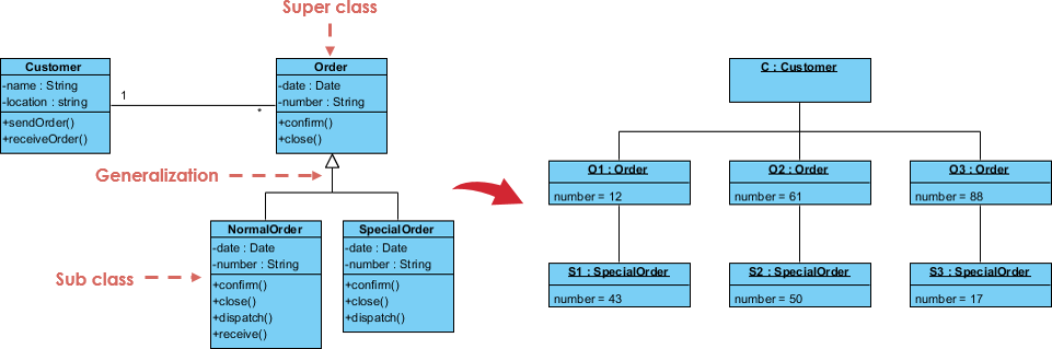
On the other hand, an object diagram is used to represent a specific instance of a class at a particular moment in time. It shows the actual objects in the system and the relationships between them. Object diagrams are useful for understanding how the different objects in the system interact with each other and can be used to debug specific instances of the system.
Here are some key differences between class diagrams and object diagrams:
- Scope: Class diagrams show the structure of the entire system, whereas object diagrams focus on a specific instance of the system.
- Level of detail: Class diagrams provide a high-level view of the system, whereas object diagrams show a more detailed view of a specific instance.
- Time: Class diagrams are created early in the development process and are used to design the system’s architecture. Object diagrams are created later in the development process and are used for debugging and testing specific instances of the system.
- Relationships: Class diagrams show the relationships between classes, whereas object diagrams show the relationships between objects.
class diagrams and object diagrams are both useful tools for software developers, but they serve different purposes. Class diagrams are used to design the system’s architecture, while object diagrams are used to debug and test specific instances of the system.
Class Diagram vs ER Diagram: Understanding the Differences and Use Cases
Class diagrams and Entity-Relationship (ER) diagrams are two popular types of diagrams used in software development to represent the structure of a system. While they share some similarities, they are used for different purposes.
A class diagram is used to represent the static structure of a software system, depicting the classes, their attributes, and their relationships with other classes. It is primarily used in object-oriented programming to design the structure of the system.
On the other hand, an ER diagram is used to represent the data structure of a system, depicting the entities, their attributes, and the relationships between them. It is primarily used in database design to model the data that will be stored in the system.
Here are some key differences between class diagrams and ER diagrams:
- Purpose: Class diagrams are used to represent the structure of a software system, while ER diagrams are used to represent the structure of a database system.
- Level of abstraction: Class diagrams are more abstract and focus on the design of the system, while ER diagrams are more concrete and focus on the data that will be stored in the system.
- Relationships: Class diagrams show the relationships between classes, while ER diagrams show the relationships between entities.
- Attributes: Class diagrams show the attributes of classes, while ER diagrams show the attributes of entities.
You would use a class diagram when designing the structure of an object-oriented system, and you would use an ER diagram when designing the structure of a database system. However, there may be cases where you need to use both diagrams to design a system that has both object-oriented and database components.
In short, class diagrams and ER diagrams are both useful tools for software developers, but they serve different purposes. Class diagrams are used to design the structure of a software system, while ER diagrams are used to design the structure of a database system.
Object Modeling and Class Diagram
Object modeling is a crucial aspect of software development as it helps in representing real-world scenarios and processes in a systematic and structured way. UML (Unified Modeling Language) is one of the most popular modeling languages used by software developers worldwide to create visual models of software systems. One of the primary components of UML is the Class diagram, which is used to model the static structure of a software system. In this article, we will discuss Object Modeling with UML Class Diagram.
UML Class Diagram for Object Modeling
A UML Class diagram is a graphical representation of a software system that depicts the classes and their relationships with other classes in the system. A class is a template or blueprint that defines the properties and behaviors of a set of objects. In other words, a class represents a category of objects that share common attributes and methods.
In UML, a class is represented as a rectangle with three compartments: the top compartment contains the class name, the middle compartment contains the attributes, and the bottom compartment contains the methods. The class name is usually written in bold, and the attributes and methods are listed in the respective compartments. The attributes are the properties of the class, and the methods are the behaviors or actions that the class can perform.
To create a Class diagram, you need to identify the classes in the system and their relationships with other classes. There are several types of relationships that can exist between classes, including association, aggregation, composition, inheritance, and dependency.
Why Classes are Essential in Object-Oriented Systems
Classes are a fundamental concept in object-oriented (OO) systems as they provide a way to represent real-world objects and their behaviors in a software system. In an OO system, objects are created from classes, which act as blueprints or templates for creating objects.
There are several reasons why we need classes in OO systems:
- Encapsulation: Classes allow us to encapsulate data and behavior into a single unit, which helps to hide the implementation details of the class and provide a clear interface for interacting with it. This encapsulation ensures that the internal state of the object cannot be accessed or modified by external code, improving the security and reliability of the system.
- Abstraction: Classes provide a way to abstract complex real-world concepts into simpler, more manageable objects in a software system. This abstraction allows us to focus on the essential properties and behaviors of an object while ignoring unnecessary details, making it easier to reason about and understand the system.
- Inheritance: Classes allow us to use inheritance to create new classes that inherit the properties and behavior of an existing class. This inheritance allows us to reuse code and avoid duplicating functionality across multiple classes, making the system more efficient and easier to maintain.
- Polymorphism: Classes allow us to use polymorphism to define multiple methods with the same name but different parameters or behaviors. This polymorphism allows us to create more flexible and adaptable systems that can respond to different inputs and scenarios.
In short, classes are a critical component of OO systems as they provide a way to represent real-world objects and their behaviors in a software system. They enable encapsulation, abstraction, inheritance, and polymorphism, which are essential principles of object-oriented design and development.
Relationships In a Class Diagram
- Association is a relationship between two classes that indicates that one class is connected to another class. It is represented by a line connecting the two classes, and it can be unidirectional or bidirectional.
- Aggregation is a relationship between two classes that indicates that one class contains or is a part of another class. It is represented by a diamond-shaped symbol on the side of the class that contains the other class.
- Composition is a stronger form of aggregation in which the containing class is responsible for the creation and destruction of the contained class. It is represented by a filled diamond-shaped symbol on the side of the class that contains the other class.
- Inheritance is a relationship between two classes that indicates that one class is a subclass of another class. It is represented by an arrow pointing from the subclass to the superclass.
- Dependency is a relationship between two classes that indicates that one class depends on another class. It is represented by a dashed arrow pointing from the dependent class to the independent class.
Once you have identified the classes and their relationships, you can start creating the Class diagram using UML notation. You can use various tools and software to create the Class diagram, such as Microsoft Visio, Eclipse, or Rational Rose.
Example – e-commerce platform for a Retail Company
Suppose you are tasked with designing a new e-commerce platform for a retail company. The company wants to allow customers to browse and purchase products online, as well as manage their account information and order history. The platform needs to be scalable, secure, and able to handle a large number of concurrent users.
To develop this platform, you need to create a detailed blueprint that describes the architecture and functionality of the system. This is where class diagrams, ER diagrams, and object diagrams come in handy.
Develop the Class Diagram
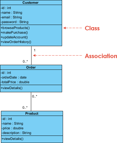
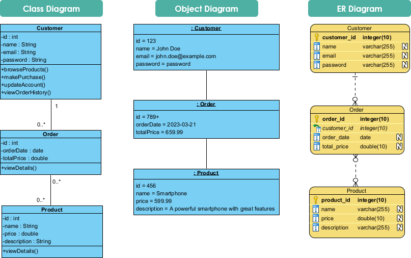
The Class Diagram as shown below, provides an overview of the classes and their relationships in an object-oriented system. In the example generated above, the classes identified include Customer, Product, and Order, each with its respective attributes and methods. The Class Diagram also indicates the relationships between classes, such as the one-to-many relationship between Customer and Order, and the many-to-many relationship between Order and Product.
Object Diagram
On the other hand, the Object Diagram below shows a specific instance of a class at a particular moment in time. It represents the objects in the system and their relationships. In the example generated above, the Object Diagram shows a specific instance of Customer, Order, and Product. The diagram indicates that the Customer object is associated with a specific Order object, and that the Order object contains specific Product objects.
Thus, the Class Diagram is used to provide an overview of the classes and their relationships, while the Object Diagram is used to represent specific instances of classes and their relationships at a particular moment in time.
Develop the ERD
The Class Diagram and ERD (Entity Relationship Diagram) are both modeling tools used to represent data structures and relationships between entities in a system.
The Class Diagram is mainly used in object-oriented systems to show the classes, their attributes, methods, and relationships with other classes. It is often used to depict the static structure of an OO system. In the example Class Diagram above, the classes identified include Customer, Product, and Order, each with their respective attributes and methods. The Class Diagram also indicates the relationships between the classes, such as the one-to-many relationship between Customer and Order, and the many-to-many relationship between Order and Product.
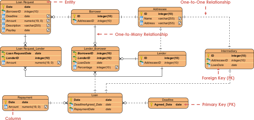
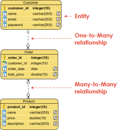
The ERD, on the other hand, is used to represent the data structure of a system and the relationships between entities in that system. It is used primarily in database systems to describe the logical structure of the database. In the example ERD below, the entities identified include Customer, Product, and Order, each with their respective attributes. The ERD also indicates the relationships between entities, such as the one-to-many relationship between Customer and Order, and the many-to-many relationship between Order and Product.
While both Class Diagram and ERD are modeling tools that represent data structures and relationships, the Class Diagram is mainly used in object-oriented systems to depict the static structure of the system, while the ERD is mainly used in database systems to describe the logical structure of the database.
Generate the Database Schema based on the ERD
Based on the Entity Relationship Diagram (ERD) generated earlier, we can create a database schema to represent the logical structure of the database.
Here is an example of a database schema based on the ERD:
Customer
– customer_id (PK)
– name
– passwordOrder
– order_id (PK)
– customer_id (FK)
– order_date
– total_priceOrder_Product
– order_id (FK, PK)
– product_id (FK, PK)
– quantityProduct
– product_id (PK)
– name
– price
– description
In this database schema, there are four tables: Customer, Order, Order_Product, and Product.
The Customer table contains information about customers, such as their name, email, and phone number. The Order table contains information about orders, such as the order date and total price, and has a foreign key constraint that references the Customer table.
The Order_Product table is a junction table that maps the many-to-many relationship between orders and products. It contains foreign keys that reference the Order and Product tables, as well as a quantity field that specifies the number of products ordered.
The Product table contains information about products, such as the product name, description, and price. It has a primary key constraint on the product_id field, which is also referenced as a foreign key in the Order_Product table.
Overall, this database schema provides a logical representation of the relationships between entities in the system, as depicted in the ERD.
Summary
This article explored the different types of diagrams used in software development to model the static aspects of an object-oriented system: class diagrams, object diagrams, and ER diagrams. Each diagram has its own specific use case and can be used at different stages of the software development process.
Class diagrams are used to model the classes in a system, their attributes, methods, and relationships. Object diagrams represent a specific instance of a class at a particular moment in time, and ER diagrams model the data structure of a system, depicting the entities, their attributes, and relationships.
Choosing the right diagram depends on the specific requirements of the software development project and the stage of the development process. Class diagrams are used in the design phase, object diagrams are used for debugging and testing specific instances of the system, and ER diagrams are used in the database design phase.
By understanding the differences and use cases of each type of diagram, software developers can choose the most appropriate diagram for their needs and ensure a successful software development project.