


Introduction:
Object diagrams are an essential part of the Unified Modeling Language (UML) used in software engineering and system design. They serve as a crucial bridge between the abstract concepts defined in class diagrams and the concrete instances of those classes during runtime. This case study explores the role of object diagrams in UML, their relationship with class diagrams, and when and how they are used in the software development process.
Background:
Before delving into the specifics of object diagrams, it’s essential to understand their connection with class diagrams, which are more commonly used. Class diagrams define the blueprint or template for objects within a system. They specify the attributes and behaviors (methods) that objects of a particular class will have. However, class diagrams do not represent actual instances of those classes; they provide a high-level, abstract view of the system’s structure.
Object Diagrams: A Snapshot in Time:
An object diagram, on the other hand, provides a snapshot of the system at a particular point in time. It shows how the classes defined in the class diagram interact with one another to create concrete instances. Object diagrams consist of objects, links, and instances of associations. Each object corresponds to a particular instance of a class, showing the specific values of its attributes at that moment. Links represent relationships or associations between objects, and multiplicity notations indicate how many instances participate in these relationships.
Purpose and Use Cases:
1. Debugging and Testing:
- Object diagrams are invaluable during the debugging and testing phases of software development. They allow developers to visualize and inspect the actual state of the system during runtime, aiding in identifying and rectifying issues.
2. Documentation:
- Object diagrams serve as effective documentation tools. They provide a clear picture of how classes interact and collaborate at runtime, making it easier for developers to understand and maintain the system.
3. Communication:
- Object diagrams facilitate communication between various stakeholders, including developers, designers, and clients. They help convey how the system behaves in real-world scenarios.
4. Design Refinement:
- When designing complex systems, object diagrams can be used to refine class diagrams. By visualizing how classes collaborate in specific situations, designers can make informed decisions about class relationships and attributes.
Example Scenario:
The Online Shopping System is a digital platform that allows users to browse, select, purchase, and receive goods or services over the internet. It has revolutionized the way people shop, offering convenience, a wide variety of products, and the flexibility to shop from the comfort of one’s own home or on the go via mobile devices. This system combines sophisticated e-commerce technology with user-friendly interfaces to create a seamless and enjoyable shopping experience.
Class Diagram – Online Shopping System
Creating a complete class diagram for an online shopping system is quite extensive due to the numerous classes, associations, and attributes involved. Instead, I will provide you with a simplified example of a class diagram that covers some of the essential classes and relationships in an online shopping system. You can use this as a starting point and expand it to suit your specific requirements.
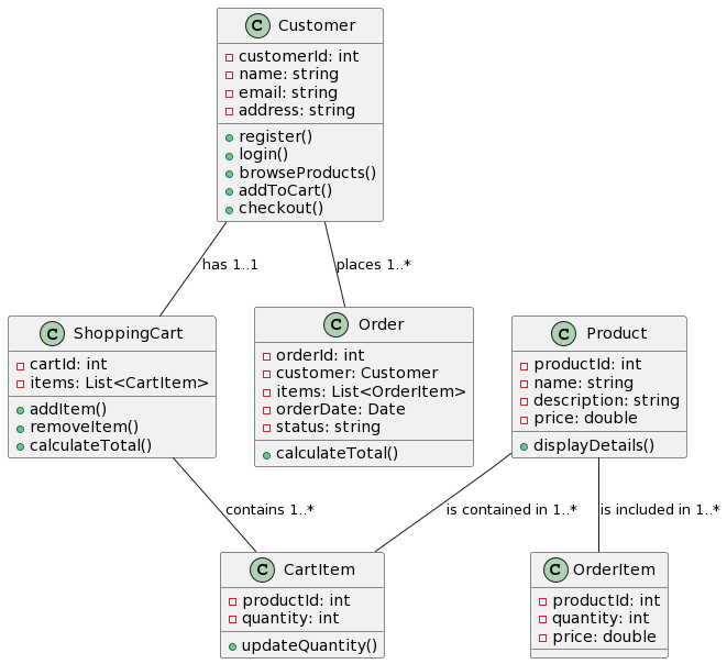
In this simplified diagram:
Customerrepresents a registered user of the online shopping system.Productrepresents the items available for purchase.ShoppingCartrepresents the shopping cart where customers can add and remove items.CartItemrepresents individual items added to the shopping cart.Orderrepresents a customer’s order, which includes multiple items.OrderItemrepresents individual items within an order.
Please note that this is a basic representation, and a real-world online shopping system would include many more classes, attributes, and relationships to capture the complexity of such a system. You can expand this diagram by adding more classes and associations to suit your specific requirements.
Object Diagram
An object diagram is typically developed to provide a snapshot of a system’s state at a specific point in time. It illustrates how instances of classes interact with each other based on the class diagram. Let’s consider an example scenario to describe when and how we would use an object diagram based on the class diagram provided for the online shopping system:
Example Scenario:
Suppose a customer, John, is using the online shopping system to make a purchase. We want to create an object diagram to capture the state of the system during this specific shopping session.
Steps to Develop an Object Diagram:
- Identify the Objects: Start by identifying the objects that are relevant to the scenario. In this case, we would need to instantiate objects for the
Customer,Product,ShoppingCart,CartItem,Order, andOrderItem. - Assign Attribute Values: Populate the objects with attribute values based on the specific situation. For example:
- Create a
Customerobject namedJohnwith his customer details. - Create a
Productobject representing the product he wants to purchase. - Create a
ShoppingCartobject to hold the selected items. - Add
CartItemobjects inside the shopping cart to represent the products added. - Create an
Orderobject to represent the order John is about to place. - Add
OrderItemobjects inside the order to represent the items within the order.
- Create a
- Establish Associations: Create associations between the objects to represent their relationships. For instance:
- Connect the
Customerobject to theShoppingCartobject to show that John owns the cart. - Connect the
ShoppingCartobject toCartItemobjects to indicate the cart’s contents. - Connect the
Productobject to the relevantCartItemorOrderItemobjects to show which products are in the cart or order.
- Connect the
- Capture the State: The object diagram captures the state of the system at the moment. Ensure that attribute values are filled in, associations are correctly represented, and multiplicity is followed.
Creating a object diagram based on the example scenario for the online shopping system can be a bit complex due to the number of objects and their associations. Below is the object diagram for this scenario:
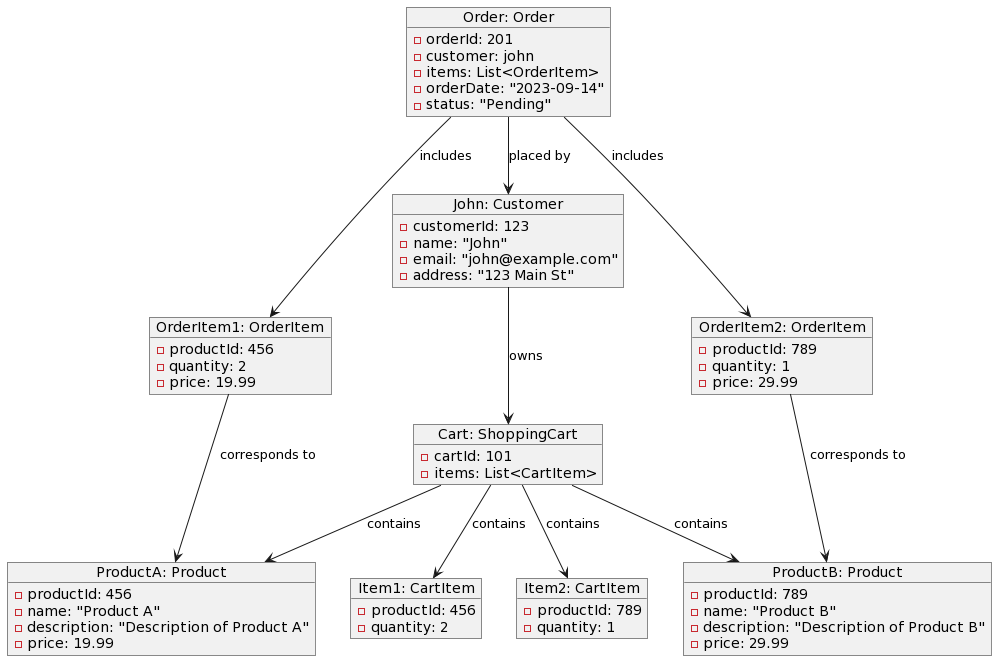
In this object diagram:
- Objects representing instances of classes are created, including
John(aCustomer),Product(aProduct),Cart(aShoppingCart),Item1(aCartItem),Order(anOrder), andOrderItem1(anOrderItem) and etc. - Associations between objects are indicated with arrows, showing ownership, containment, and other relationships.
- Attribute values for the objects are specified to represent the state of the system at this specific point in time.
Please note that this is a simplified representation, and in a real-world scenario, there would be more objects, associations, and attributes to capture the full system state. You can expand this diagram to include additional objects and their relationships as needed.
Conclusion
In the world of software engineering and system design, object diagrams play a vital role in bridging the gap between abstract class definitions and real-world instances during runtime. As demonstrated in our exploration of the online shopping system, object diagrams serve as powerful tools for capturing and visualizing the system’s state at specific moments, enabling developers, testers, and stakeholders to gain valuable insights and achieve various objectives.
Through our discussion, we have highlighted the following key points:
- Object Diagrams as Snapshots: Object diagrams provide a snapshot of the system’s state, showcasing how objects interact and collaborate at a specific point in time. They offer a dynamic perspective on a system built upon the foundation of class diagrams.
- Use Cases of Object Diagrams: Object diagrams find their utility in a range of scenarios, including debugging, testing, documentation, communication, and design validation. They help identify issues, verify system behavior, facilitate communication among team members, and ensure that the class diagram is correctly implemented in real-world situations.
- Integration with Class Diagrams: Object diagrams complement class diagrams, allowing us to see how abstract class structures translate into tangible instances during runtime. The synergy between these two UML diagram types provides a comprehensive understanding of a software system, both structurally and behaviorally.
- Flexibility in Representation: Object diagrams can be as simple or complex as needed, depending on the specific scenario. They allow for the representation of object states, associations, attributes, and multiplicity, making them adaptable to various use cases.
Object diagrams empower software engineers and designers to delve deeper into the intricacies of their systems, providing a tangible view of abstract concepts. Whether used for fine-tuning a system’s design, pinpointing bugs, or conveying system behavior to stakeholders, object diagrams are invaluable tools in the software development toolkit, helping teams build robust and reliable software systems.