


Introduction
Data modeling plays a critical role in the development of information technology (IT) systems. It involves creating abstract representations of the data that an application will use, which helps developers design efficient databases and understand the relationships between different data elements. Two commonly used modeling techniques are Class Diagrams and Entity-Relationship Diagrams (ERDs). While Class Diagrams are commonly associated with object-oriented programming, ERDs are used in database design. This article explores the process of elaborating a Class Diagram into an ERD to facilitate effective data modeling for an IT system.
Understanding Class Diagrams
Class Diagrams are a fundamental part of object-oriented design and are often used during the early stages of software development. They depict the static structure of a system by representing classes, their attributes, methods, and the relationships between classes. Class Diagrams are useful for modeling the logical structure of an application but do not delve into the details of data storage.
Understanding Entity-Relationship Diagrams (ERDs)
On the other hand, ERDs are used specifically for database design and focus on the relationships between entities (tables) and the attributes (fields) within those entities. ERDs provide a clear visual representation of the database schema, allowing developers to see how data is organized, connected, and related within the system.
Why Transition from Class Diagram to ERD?
While Class Diagrams are excellent for illustrating the high-level architecture of an IT system, they often lack the detail needed for database design. Transitioning from a Class Diagram to an ERD is necessary because:
- Data Modeling Precision: ERDs provide a more detailed and precise representation of data elements, including their attributes, data types, and relationships. This level of detail is crucial for database design and implementation.
- Database Optimization: ERDs help in identifying potential issues such as redundancy, normalization, and data integrity constraints, enabling the creation of efficient database structures.
- Clear Database Schema: ERDs create a clear visual representation of the database schema, making it easier for developers and database administrators to understand the data structure and relationships.
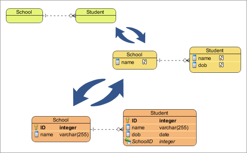
Steps to Elaborate a Class Diagram into an ERD
- Identify Classes and Entities: Start by identifying the classes in your Class Diagram that represent persistent data. These classes will become entities in your ERD.
- Define Attributes: For each entity, list and define its attributes. In the ERD, these attributes will become fields in the corresponding entity table.
- Specify Relationships: Identify relationships between entities in your Class Diagram. In the ERD, represent these relationships using lines connecting the entity tables. Use cardinality notation to define the nature of the relationships (e.g., one-to-one, one-to-many, many-to-many).
- Normalize Data: Normalize the data to minimize redundancy and improve data integrity. Ensure that data is organized into tables to adhere to the principles of normalization.
- Incorporate Constraints: Add constraints such as primary keys, foreign keys, and unique constraints to enforce data integrity.
- Review and Refine: Carefully review your ERD to ensure that it accurately reflects the data model. Make refinements as necessary to align it with the requirements of the IT system.
Conclusion
In the realm of data modeling, the symbiotic relationship between object-oriented design, represented through class diagrams, and the relational database management system (RDBMS), exemplified by Entity-Relationship Diagrams (ERDs), is paramount. Object-oriented design encapsulates the logical structure of an IT system, defining classes, their attributes, and methods. Yet, for effective data storage and retrieval, a transition to the ERD paradigm becomes indispensable. ERDs, tailored for RDBMS, bridge the gap between the abstract world of classes and the concrete database schema, illustrating how objects are transformed into tables, attributes into fields, and class relationships into referential integrity constraints. This synergy ensures that an IT system not only adheres to sound software engineering principles but also maintains data integrity and efficiency throughout its lifecycle.
Transitioning from a Class Diagram to an Entity-Relationship Diagram is a crucial step in the data modeling process for IT systems. While Class Diagrams provide an excellent high-level view of the system’s architecture, ERDs offer the detailed representation needed for database design, optimization, and data integrity. By following the steps outlined in this article, developers can effectively elaborate their Class Diagrams into ERDs, creating a strong foundation for building robust and efficient IT systems.