


Introduction
Unified Modeling Language (UML) stands as a universal language for visualizing, specifying, constructing, and documenting the artifacts of software systems. Within the expansive realm of UML, the Sequence Diagram emerges as a powerful tool for portraying the dynamic interactions between various components within a system.
In this article, we will dissect the Sequence Diagram Notation, unraveling the symbols and conventions employed to depict the intricate dance of entities, messages, and lifelines. Understanding this notation is pivotal for anyone involved in the design, analysis, or implementation of complex systems, as it provides a standardized visual language that transcends technical boundaries.
Sequence Diagrams in UML
In Unified Modeling Language (UML), a Sequence Diagram is a graphical representation that illustrates the interactions and dynamic behaviors between various components or objects within a system over a specific period. It provides a time-ordered sequence of events, showcasing the flow of messages and the lifeline of each participant.
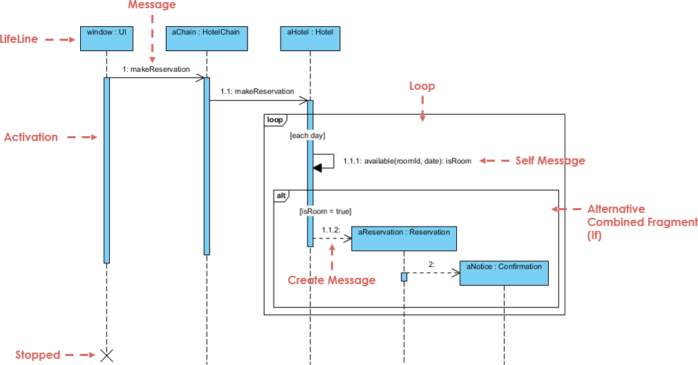
Here are key elements and concepts within a UML Sequence Diagram:
1. Actors
Notation Description: An actor represents a type of role played by an entity external to the subject. Actors interact with the subject by exchanging signals and data. They can be human users, external hardware, or other subjects.
Visual Representation:
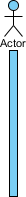
Note: Actors do not necessarily represent specific physical entities but rather specific roles of entities.
2. Lifeline
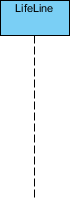
Notation Description: A lifeline represents an individual participant in the interaction. It essentially portrays the existence of an entity over time during the interaction.
Visual Representation:
3. Activations
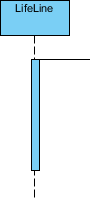
Notation Description: A thin rectangle on a lifeline represents the period during which an element is performing an operation. The top and bottom of the rectangle align with the initiation and completion time, respectively.
Visual Representation:
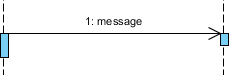
4. Call Message
Notation Description: A call message is a type of message that represents the invocation of an operation on the target lifeline.
Visual Representation:
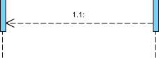
5. Return Message
Notation Description: A return message represents the passing of information back to the caller of a corresponding former messag
Visual Representation:
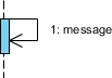
6. Self Message
Notation Description: A self message represents the invocation of a message on the same lifeline.
Visual Representation:
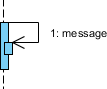
7. Recursive Message
Notation Description: A recursive message represents the invocation of a message on the same lifeline. The target points to an activation on top of the activation where the message was invoked from.
Visual Representation:
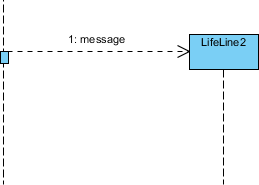
8. Create Message
Notation Description: A create message represents the instantiation of a target lifeline.
Visual Representation:
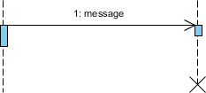
9. Destroy Message
Notation Description: A destroy message represents the request for destroying the lifecycle of the target lifeline.
Visual Representation:
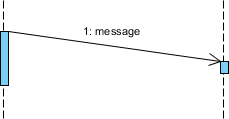
10. Duration Message
Notation Description: A duration message shows the distance between two time instants for a message invocation.
Visual Representation:
11. Note
Notation Description: A note or comment provides the ability to attach various remarks to elements, carrying no semantic force but containing useful information for modelers.
Visual Representation:

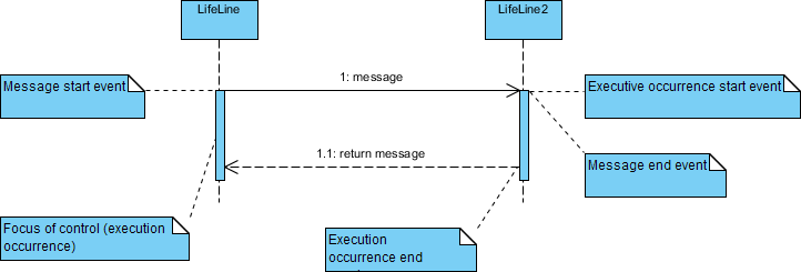
12. Message and Focus of Control
Notation Description: An event is any point in an interaction where something occurs. Focus of control, also called execution occurrence, is represented as a tall, thin rectangle on a lifeline.
Visual Representation:
13. Sequence Fragments
Notation Description: Sequence fragments, represented as combined fragments, make it easier to create and maintain accurate sequence diagrams.
Visual Representation:
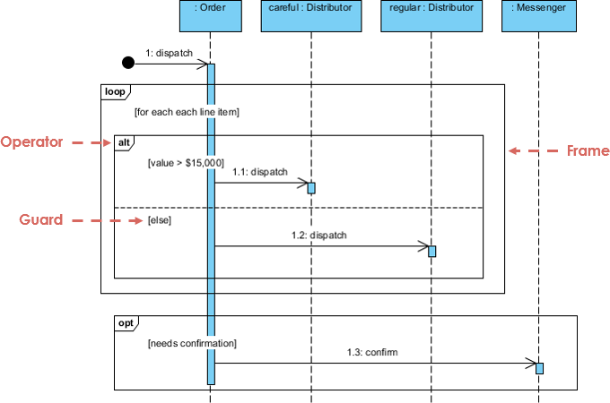
Fragment Types and Operators:
alt: Alternative multiple fragments, only the one whose condition is true will execute.opt: Optional fragment, executes only if the supplied condition is true.par: Parallel fragment, each fragment runs in parallel.loop: Loop fragment, may execute multiple times.region: Critical region fragment, only one thread can execute it at once.neg: Negative fragment, shows an invalid interaction.ref: Reference fragment, refers to an interaction defined on another diagram.sd: Sequence diagram fragment, used to surround an entire sequence diagram.
Note: Combined fragments can be combined to capture loops or branches.
A typical use of Sequence Diagrams is in capturing and visualizing the interactions between objects or actors as they collaborate to achieve a particular functionality or use case. They are particularly useful in system design, analysis, and communication between stakeholders, providing a high-level overview of the dynamic aspects of a system.
In essence, a UML Sequence Diagram is a powerful tool that aids in understanding the chronological order of interactions between components, helping developers and stakeholders visualize the dynamic behavior of a system and facilitating effective communication during the software development process.
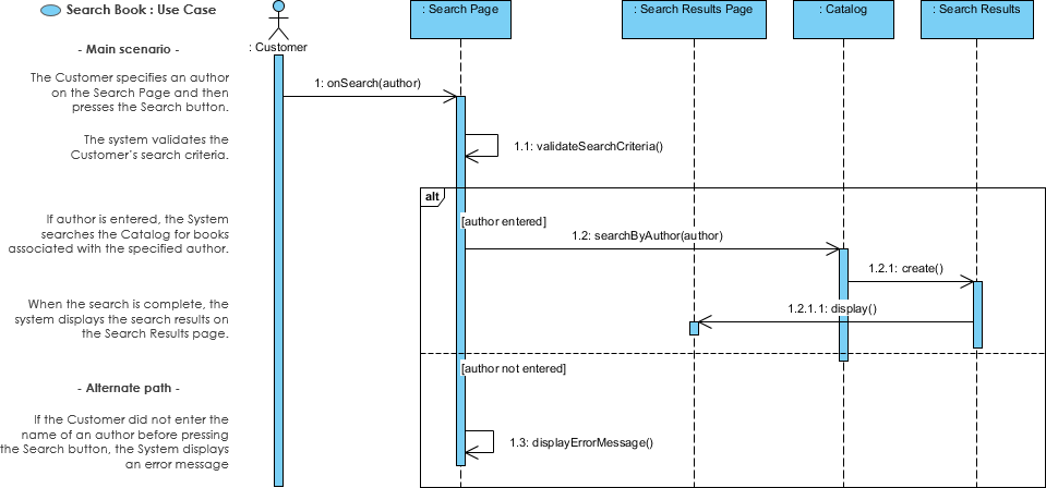
14. Sequence Diagram for Modeling Use Case Scenarios
Notation Description: User requirements are captured as use cases that are refined into scenarios. A use case is a collection of interactions between external actors and a system.
Visual Representation:
15. Sequence Diagram – Model before Code
Notation Description: Sequence diagrams serve as a bridge between user requirements and system implementation. They are somewhat close to the code level but offer language-neutral representations that non-coders can understand.
Visual Representation:
Conclusion
UML Sequence Diagram serves as a crucial visual tool within Unified Modeling Language (UML) to depict the dynamic interactions and behaviors of components within a system. It captures the chronological order of events and messages exchanged between lifelines, which represent individual participants in the interaction, be they objects or actors. The diagram includes various types of messages such as Call, Return, Self, Recursive, Create, Destroy, and Duration Messages, each conveying specific actions and interactions.
The notational elements, including activations, combined fragments, and notes, provide a comprehensive language for expressing complex system behaviors. Activations represent the periods during which elements perform operations, while combined fragments introduce conditional and iterative behaviors.
The Sequence Diagram’s utility extends to modeling use case scenarios, capturing user requirements, and offering a bridge between high-level system design and implementation. It provides a standardized and language-neutral representation, facilitating communication among developers, designers, and other stakeholders. The diagram’s versatility makes it a valuable tool for teams, allowing for collaborative modeling, testing, and UX wireframing, even for those who may not be proficient in coding. In essence, the UML Sequence Diagram serves as a visual storyteller, unveiling the intricate dance of entities and messages that define the dynamic essence of a software system.