


Introduction
Data-flow diagrams (DFDs) serve as a crucial tool in the realm of software engineering, providing a visual representation of how data moves within a system. However, the complexity of creating these diagrams necessitates a thorough validation process to ensure accuracy and clarity. Here, we’ll explore a set of questions and considerations to guide you in validating your DFDs effectively.
Single Diagram Validation
- Connection Check:
- Ensure that every data-flow is properly connected to a process at either the beginning or end of the arrow. This ensures a clear flow of data between processes and entities.
Example: In a banking system DFD, verify that the arrow representing “Customer Withdrawal Request” is connected to the “Process: Withdrawal Processing.”
- Labeling Clarity:
- Confirm that each data-flow is labeled with a sensible noun, contributing to a clear understanding of the information being conveyed.
Example: Instead of a vague label, such as “Data Flow 1,” use “Customer Details” for better comprehension.
- Process Inputs and Outputs:
- Validate that every process has at least one input and one output, ensuring that processes are adequately handling data.
Example: In an online shopping system, verify that the “Process: Order Fulfillment” has inputs like “Customer Order” and outputs like “Shipped Order.”
- Process Naming Conventions:
- Check if every process is named sensibly, following the template “Do something to something,” and avoiding generic terms like “process” or “handle.”
Example: Instead of “Processing,” use “Validate Payment” to clearly depict the action performed by the process.
- Data Store Naming:
- Confirm that data stores are named with the type of items they store, using plural terms for clarity.
Example: Instead of “Order Data,” use “Orders Database” to indicate that it stores multiple orders.
- Consistency in Representation:
- When showing data stores and external entities multiple times, ensure that each instance has a “diagonal” line, maintaining consistency.
Example: In a manufacturing DFD, if “Supplier” is shown twice, both instances should have a diagonal line.
- Avoiding Data Flow Crossings:
- Identify and address any data-flows that cross, aiming to add duplicate external entities or data stores to prevent crossing.
Example: If “Customer Data” and “Order Details” cross paths, consider introducing separate instances or refining the connections.
Set of Diagrams Validation
- Balancing Expansion:
- Confirm that all diagrams balance when a process is expanded. Inputs and outputs at higher levels should align with those at lower levels.
Example: If a level two diagram expands on “Payment Processing,” ensure that the inputs and outputs match the corresponding process on the level one diagram.
- Consistent Entity Representation:
- Verify that all external entities are consistently represented on both the context diagram and level one diagram.
Example: If “Customer” is shown as an external entity on the context diagram, it should also appear on the level one diagram.
- Correct Numbering:
- Ensure that all processes and data stores are numbered correctly for easy reference and navigation.
Example: If a process is numbered as “P3” on one diagram, it should maintain the same numbering throughout.
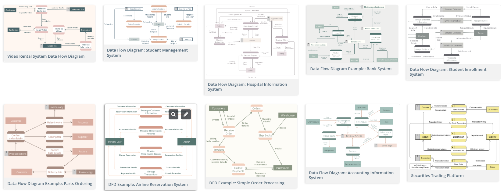
Data Flow Diagram Templates
Jumpstart your design with professional data flow diagram templates by Visual Paradigm:
Conclusion
while DFDs enhance communication between software engineers and stakeholders, their effectiveness relies on meticulous validation. As the diagrams evolve, periodic reviews and rearrangements become essential to maintain clarity and prevent communication breakdowns. A clean and well-validated data-flow model not only ensures technical accuracy but also enhances the overall communication process in software development projects.