Object Diagram in UML: Bridging the Gap Between Classes and Instances

Object Diagram in UML: Bridging the Gap Between Classes and Instances

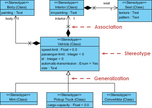
Introduction: Object diagrams are an essential part of the Unified Modeling Language (UML) used in software engineering and system design. They serve as a crucial bridge between the abstract concepts defined in class diagrams and the concrete instances of those classes during runtime. This case study explores the role of object diagrams in UML, their relationship with class diagrams, and when and how they are used in the software development process. Background: Before delving into the specifics of object diagrams, it's essential to understand their connection with class diagrams, which are more commonly…continue reading →
Understanding Profile Diagrams in UML: A Comprehensive Guide

Understanding Profile Diagrams in UML: A Comprehensive Guide

Unified Modeling Language (UML) is a powerful tool used by software engineers and designers to visualize, document, and communicate the various aspects of a software system. UML offers a wide range of diagram types, each designed to represent specific aspects of a system's architecture and behavior. Among these, the Profile Diagram stands out as a specialized diagram that allows users to extend UML to meet their specific modeling needs. In this article, we will delve into the world of Profile Diagrams in UML, exploring their purpose, elements, and how they can enhance the…continue reading →
Choosing the Right UML Diagram: State Diagrams, Sequence Diagrams, or Activity Diagrams?

Choosing the Right UML Diagram: State Diagrams, Sequence Diagrams, or Activity Diagrams?

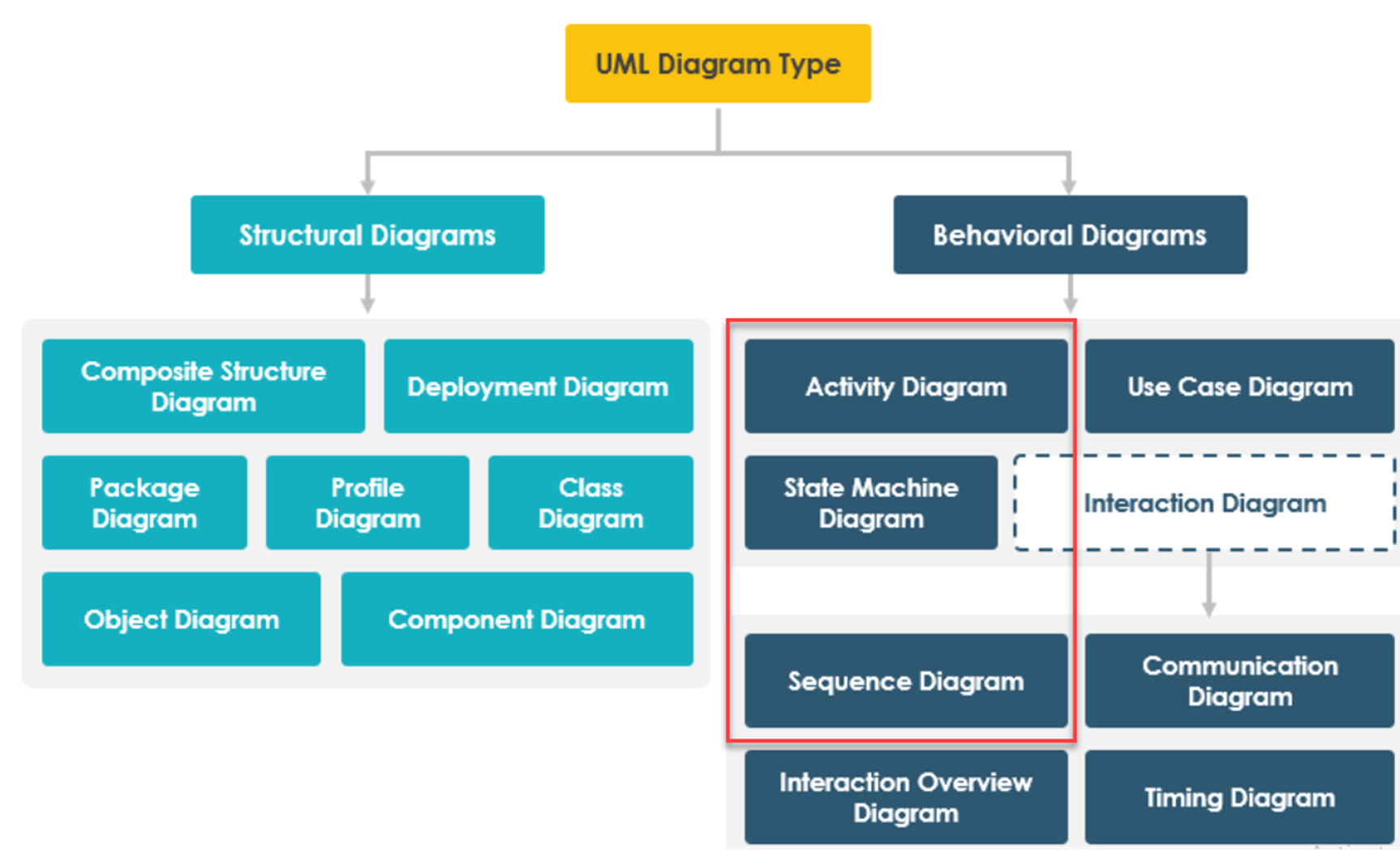
Introduction Unified Modeling Language (UML) provides a powerful set of tools for modeling various aspects of a system or software application. However, deciding which UML diagram to use can be challenging, as different diagrams serve different purposes. In this guide, we will explore three key UML diagram types: State Diagrams, Sequence Diagrams, and Activity Diagrams. We will help you understand when and why to use each type, providing clarity on their specific use cases and advantages. State Diagrams focus on modeling the states and state transitions of an object or system. Sequence Diagrams…continue reading →
A Comparative Analysis of Activity Diagrams and BPMN in UML

A Comparative Analysis of Activity Diagrams and BPMN in UML

Introduction Unified Modeling Language (UML) is a widely used visual modeling language in software engineering and business process management. It provides various diagrams to represent different aspects of a system or a process. Two commonly used UML diagrams for modeling processes are Activity Diagrams and Business Process Model and Notation (BPMN). While both serve the purpose of process modeling, they have distinct characteristics and use cases. This article aims to compare and contrast Activity Diagrams and BPMN in UML to help you choose the most suitable diagram for your modeling needs. Activity Diagrams…continue reading →
Navigating Scope: The Impact of Cloud, Kite, Sea, Fish, Clam in Use Case Analysis

Navigating Scope: The Impact of Cloud, Kite, Sea, Fish, Clam in Use Case Analysis

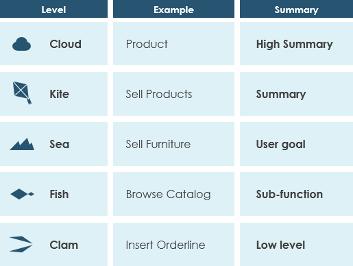
Introduction In the dynamic world of software development, managing scope is a critical challenge. The concept of "Cloud, Kite, Sea, Fish, Clam" offers a unique lens through which we can understand and approach this challenge. This model, developed by Alistair Cockburn, provides a structured framework for breaking down and assessing the scope of software projects at various levels of granularity. In this article, we delve into how these scope levels affect the software development process, from project planning to resource allocation, communication, and beyond. Join us as we explore the profound impact of…continue reading →
Component Diagram vs deployment Diagram in UML

Component Diagram vs deployment Diagram in UML

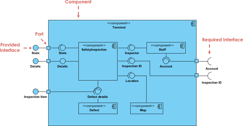
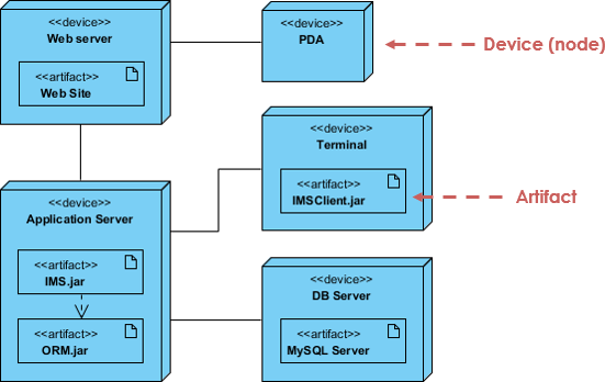
Component diagrams and deployment diagrams are two types of diagrams used in the Unified Modeling Language (UML) to model different aspects of a software system. They serve different purposes and focus on different aspects of system design and implementation. Component Diagram Purpose: Component diagrams are primarily used to represent the high-level structure of a software system in terms of its components and their relationships. They focus on the organization and modularization of the software system. Elements: Component diagrams include components, interfaces, connectors, and dependencies. Components: These represent the major building blocks or modules…continue reading →
Modeling a Client/Server System using UML Packages and Deployment Diagram

Modeling a Client/Server System using UML Packages and Deployment Diagram

Unified Modeling Language (UML) is a powerful tool for visualizing, designing, and documenting software systems. When it comes to modeling complex systems like client/server architectures, UML offers various diagrams to represent different aspects of the system. In this article, we will focus on using UML packages and deployment diagrams to model a client/server system. Understanding Client/Server Systems Before we dive into the UML modeling aspect, let's briefly understand what a client/server system is. In a client/server architecture, a networked system is divided into two main components: Client: The client is a user interface…continue reading →
TOGAF ADM: Top 10 techniques – Part 10: Capability-based planning

TOGAF ADM: Top 10 techniques – Part 10: Capability-based planning

Capability-based planning is a business-focused approach to strategic planning that aims to deliver the required capabilities to an organization. It brings together all lines of business to achieve a shared goal, and is particularly useful in organizations where resources are involved in multiple capabilities, such as emergency preparedness units. From an IT perspective, capability-based planning is highly relevant, especially when it comes to setting up a data center. This is because IT architects and planners are often involved in managing not just the IT implementation, but also other tasks such as personnel training…continue reading →
Structuring Use Cases with Base, Include, and Extend: A Guide for Effective Software Development

Structuring Use Cases with Base, Include, and Extend: A Guide for Effective Software Development

What is Use Case Modeling Use cases are an important tool in the field of software development, as they help to specify how a user will interact with a particular system. They provide a clear and concise way to document the functionality of a system, and can be used to ensure that developers are building software that meets the needs of its intended users. When creating use cases, it is important to structure them in a way that makes them easy to understand and implement. One way to do this is to use…continue reading →
Mastering ER Modeling: A Step-by-Step Guide with Real-World Examples (Part 3 of 5)

Mastering ER Modeling: A Step-by-Step Guide with Real-World Examples (Part 3 of 5)

Problem Statement: Hospital System The hospital currently relies on a paper-based system to manage patient information, medical records, and billing. The paper-based system has several limitations, including difficulty in accessing patient information in a timely manner, increased risk of data loss or misplacement, and errors in billing and medical record keeping. As a result, the hospital has decided to develop an electronic health record system to improve the efficiency and accuracy of their operations. The new electronic health record system should be able to store and manage patient demographic information, medical history, diagnostic…continue reading →