Home » Archives for September 2023 » Page 14
-
Posted on September 12, 2023
-
/Under UML
Distinguishing Between Models, Diagrams, and Views in UML In UML (Unified Modeling Language), "diagram," "view," and "model" are related concepts that play different roles in modeling and representing various aspects of a system. Let's clarify each of these terms: Model: A model in UML represents an abstract, conceptual description of a system or a part of a system. It serves as the foundation for understanding and communicating the system's structure, behavior, and interactions. A UML model can encompass a wide range of information, including class definitions, relationships, use cases, state machines, sequence diagrams,…
continue reading →
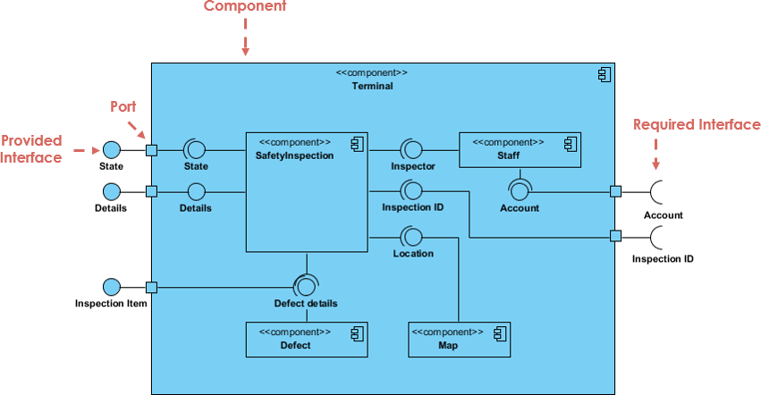
Component diagrams and deployment diagrams are two types of diagrams used in the Unified Modeling Language (UML) to model different aspects of a software system. They serve different purposes and focus on different aspects of system design and implementation. Component Diagram Purpose: Component diagrams are primarily used to represent the high-level structure of a software system in terms of its components and their relationships. They focus on the organization and modularization of the software system. Elements: Component diagrams include components, interfaces, connectors, and dependencies. Components: These represent the major building blocks or modules…
continue reading →
Introduction In the realm of software engineering and system design, creating a comprehensive and well-structured architecture is essential for building complex systems. Unified Modeling Language (UML) is a powerful tool that facilitates the visualization and documentation of system architectures. One widely adopted approach for modeling system architectures using UML is the "4 + 1" view model. This model offers a holistic perspective on system architecture, breaking it down into five distinct views that collectively provide a comprehensive understanding of the system. In this article, we will explore the concept of the "4 +…
continue reading →
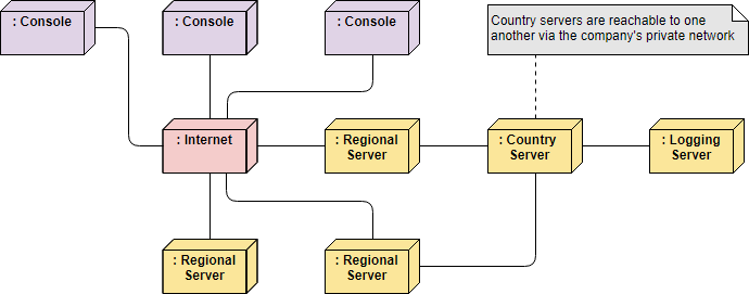
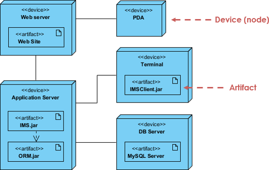
UML Deployment Diagrams: Modeling Distributed System Architecture A UML Deployment Diagram is a type of diagram in the Unified Modeling Language (UML) that is used to model the physical deployment of software components and their relationships in a system. It primarily focuses on representing the hardware and software nodes in a system and how software artifacts are allocated to those nodes. While deployment diagrams can be useful for modeling parts of a distributed system, they may have limitations when modeling a fully distributed system. Here are some key points to consider when using…
continue reading →
Unified Modeling Language (UML) is a powerful tool for visualizing, designing, and documenting software systems. When it comes to modeling complex systems like client/server architectures, UML offers various diagrams to represent different aspects of the system. In this article, we will focus on using UML packages and deployment diagrams to model a client/server system. Understanding Client/Server Systems Before we dive into the UML modeling aspect, let's briefly understand what a client/server system is. In a client/server architecture, a networked system is divided into two main components: Client: The client is a user interface…
continue reading →
-
Posted on September 12, 2023
-
/Under UML
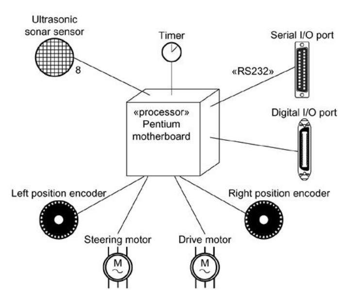
What is an Embedded System? An embedded system is a specialized computer system that is designed to perform dedicated functions or tasks within a larger system or product. Unlike general-purpose computers, which are versatile and can run a wide range of applications, embedded systems are tailored for specific functions and are typically optimized for performance, power efficiency, and reliability within their designated application domain. Key characteristics of embedded systems include: Dedicated Functionality: Embedded systems are purpose-built to perform one or a few specific tasks, such as controlling a microwave oven, managing the engine…
continue reading →
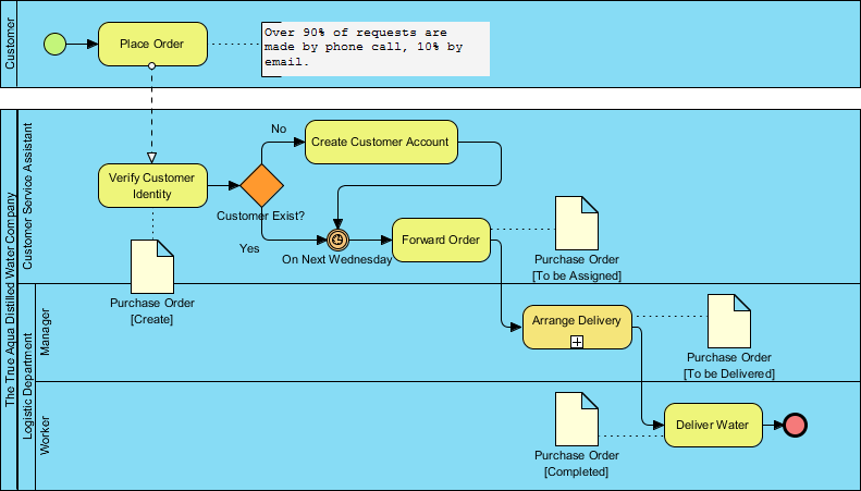
What is BPMN Business Modeling delves into the foundational concepts and components of BPMN (Business Process Model and Notation), a widely adopted framework for visually representing and documenting business processes. In this comprehensive exploration, we navigate through key aspects, starting with the definition of business goals and their intricate connection to related business processes. Understanding that a business process comprises a coordinated set of activities performed within a defined framework is essential to appreciating the significance of BPMN. BPMN was introduced with a primary aim: to offer a universal notation system that bridges…
continue reading →
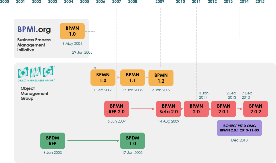
BPMN, which stands for Business Process Model and Notation, is a widely adopted and standardized modeling language for representing business processes. BPMN was originally developed by the Business Process Management Initiative (BPMI) and is currently maintained by the Object Management Group (OMG). In 2005, these two entities merged, leading to subsequent updates in the BPMN standard. The latest version, known as BPMN 2.0, was introduced in 2011 with the objective of establishing a unified specification for creating Business Process Model and Notation diagrams. This latest iteration introduced additional levels of detail, including features…
continue reading →
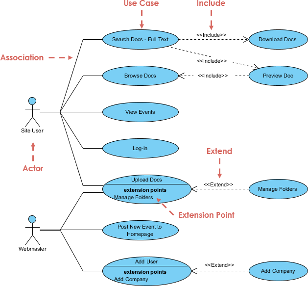
What is Use Case Modeling? This is a technique used in software development and systems engineering to describe the functional requirements of a system. It focuses on understanding and documenting how a system is supposed to work from the perspective of the end users. In essence, it helps answer the question: "What should the system do to meet the needs and goals of its users?" Key Concepts of Use Case Modeling Functional Requirements: Functional requirements are the features, actions, and behaviors a system must have to fulfill its intended purpose. Use case modeling…
continue reading →

