Home » Archives for September 2023 » Page 13
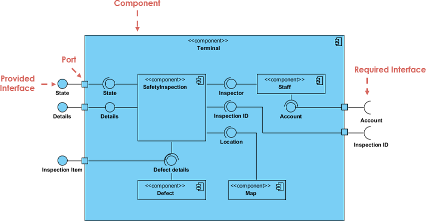
UML (Unified Modeling Language) component diagrams are indeed a valuable tool in software engineering for modeling high-level software components and subsystems. They are especially useful in service-oriented architectures and component-based development projects. Here are some key points about UML component diagrams: Modeling Components: UML component diagrams allow you to represent the major software components or modules within a system. These components can be classes, libraries, packages, or even larger subsystems, depending on the granularity of the system you are modeling. Defining Interfaces: One of the primary purposes of component diagrams is to define…
continue reading →
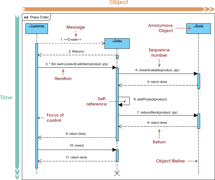
Introduction In the realm of software development, effective communication and collaboration are paramount. Developers, designers, and stakeholders must work together seamlessly to create robust and efficient software systems. One of the most powerful tools for visualizing and documenting these interactions is the sequence diagram. In this article, we will delve into the world of sequence diagrams, exploring their purpose, components, and best practices for creating them. What is a Sequence Diagram? A sequence diagram is a graphical representation of the interactions between various objects or components within a software system over a specific…
continue reading →
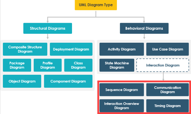
Introduction In UML (Unified Modeling Language), interaction diagrams are a category of diagrams used to visualize and describe the dynamic aspects of a system or software application. These diagrams focus on illustrating how different objects or components within the system interact with each other over time. Interaction diagrams are particularly useful for modeling and understanding the flow of messages, actions, and events that occur during the execution of a use case or scenario. Interaction diagrams are essential tools in UML for capturing and communicating the dynamic behavior of a system. They help software…
continue reading →
Introduction In the realm of software engineering and system modeling, the Unified Modeling Language (UML) serves as a vital tool for visualizing, designing, and documenting complex systems. UML offers various diagram types to address different aspects of a system's structure and behavior. Among these, Interaction Overview Diagrams, Interaction Diagrams (Sequence and Communication Diagrams), and Activity Diagrams hold significant prominence. Each of these diagram types serves a distinct purpose and provides unique insights into system dynamics. In this comparative analysis, we will explore and contrast these UML diagrams, shedding light on their intended use,…
continue reading →
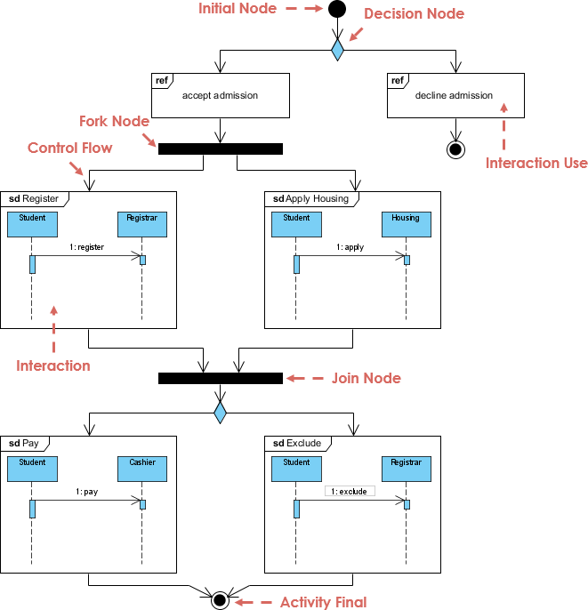
Introduction Interaction Overview Diagram is a behavioral diagram within the Unified Modeling Language (UML) that serves to illustrate the control flow among various interactions or interaction fragments within a system. Its primary function is to offer a bird's-eye view of how interactions interact and control flows within individual interactions or sequence diagrams are organized. Interaction Overview Diagrams prove invaluable when tackling intricate systems housing multiple interactions, assisting in their coordination and organization. Purpose and Role: The fundamental purpose of an Interaction Overview Diagram is to depict the control flow between diverse interactions and…
continue reading →
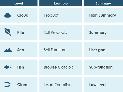
Introduction In the dynamic world of software development, managing scope is a critical challenge. The concept of "Cloud, Kite, Sea, Fish, Clam" offers a unique lens through which we can understand and approach this challenge. This model, developed by Alistair Cockburn, provides a structured framework for breaking down and assessing the scope of software projects at various levels of granularity. In this article, we delve into how these scope levels affect the software development process, from project planning to resource allocation, communication, and beyond. Join us as we explore the profound impact of…
continue reading →
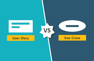
Introduction Use Case and User Story are two different techniques used in Agile software development to capture and communicate requirements, and they serve slightly different purposes. Whether one is better than the other depends on the specific needs and preferences of the Agile team and the project context. Let's explore the differences and use cases for each: Use Case: Purpose: Use cases are typically used to describe the functional requirements of a system from the perspective of an external actor (usually a user or another system). Format: They are often represented as structured…
continue reading →
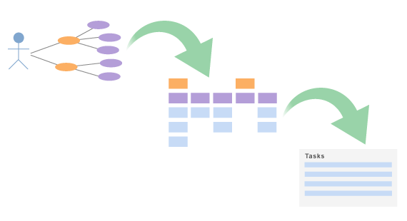
Introduction Agile development methodologies have revolutionized the software development landscape by emphasizing collaboration, adaptability, and iterative development. While Agile practices like Scrum and Kanban have gained widespread adoption, it's crucial not to overlook the importance of effective requirements management in Agile projects. Use case modeling serves as a valuable bridge between customer needs and software implementation in Agile development. In this article, we will explore how to effectively apply use case modeling in Agile projects to enhance communication, streamline development, and deliver high-quality software. The Role of Use Case Modeling in Agile Use…
continue reading →
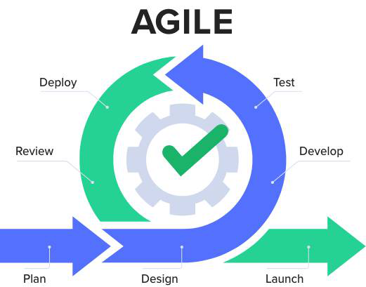
Introduction Agile methodologies like Scrum and Kanban have gained immense popularity in the software development industry for their flexibility and ability to adapt to changing requirements. However, many developers and teams wonder how to incorporate UML (Unified Modeling Language) modeling into their agile processes effectively. UML provides a powerful toolset for visualizing and designing software systems, which can enhance communication, design, and documentation. In this article, we will explore strategies for integrating UML modeling into Scrum and Kanban workflows. The Role of UML in Agile Development Before diving into integration strategies, let's understand…
continue reading →
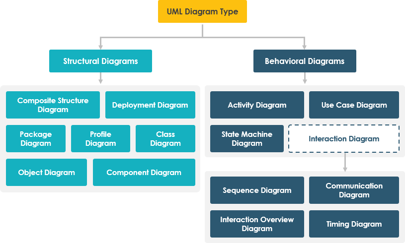
In UML, diagrams can be broadly categorized into two main categories: structure diagrams and behavior diagrams. Here's a brief description of each of the 14 types of diagrams and their categorization: Structure Diagrams (Static Modeling): Class Diagram (Structure): Represents the static structure of a system, including classes, attributes, and relationships. Object Diagram (Structure): Shows a snapshot of instances at a specific point in time, depicting objects and their relationships. Package Diagram (Structure): Organizes elements into packages, providing a high-level view of the system's organization. Component Diagram (Structure): Focuses on system components and their…
continue reading →

